Lexus NX: Removal
REMOVAL
PROCEDURE
1. REMOVE DOOR SCUFF PLATE ASSEMBLY LH
Click here .gif)
2. REMOVE COWL SIDE TRIM BOARD LH
Click here
3. REMOVE NO. 1 INSTRUMENT PANEL UNDER COVER SUB-ASSEMBLY
Click here
4. REMOVE GLOVE COMPARTMENT DOOR ASSEMBLY
Click here
5. REMOVE ACCELERATION SENSOR
(a) for RH side:
| (1) Disconnect the connector from the acceleration sensor. |
|
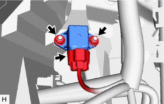
(2) Remove the 2 nuts and acceleration sensor.
NOTICE:
- Avoid any impact to the acceleration sensor.
- Do not drop the acceleration sensor. If it is dropped, replace it with a new one.
(b) for LH side:
| (1) Disconnect the connector from the acceleration sensor. |
|
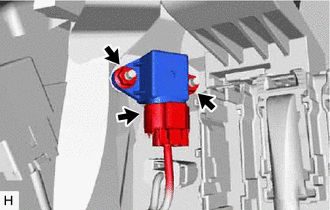
(2) Remove the 2 nuts and acceleration sensor.
NOTICE:
- Avoid any impact to the acceleration sensor.
- Do not drop the acceleration sensor. If it is dropped, replace it with a new one.
READ NEXT:
 Inspection
INSPECTION PROCEDURE 1. INSPECT ACCELERATION SENSOR (a) Connect 3 1.5 V dry cell batteries in series. (b) Connect a positive (+) lead from the batteries to terminal 3 (SGB) and a negative (-) lead to
Installation
INSTALLATION PROCEDURE 1. INSTALL ACCELERATION SENSOR (a) for RH side: (1) Install the acceleration sensor with the 2 nuts. Torque: 8.5 N·m {87 kgf·cm, 75 in·lbf} NOTICE:
Avoid any impact to th
SEE MORE:
Precaution
PRECAUTION PRECAUTIONS DURING REPLACEMENT NOTICE: When replacing electronic parts, if there is a possibility that your body may contact a circuit board, etc., use the recommended tools and observe all precautions to prevent damage to the system by electrostatic discharge (ESD). (a) Procedures where
Essential information
Emergency flashers
The emergency flashers are used to
warn other drivers when the vehicle
has to be stopped in the road due to
a breakdown, etc.
Operating instructions
Press the switch.
All the turn signal lights will flash. To turn
them off, press the switch once again.
■Emergency
© 2016-2026 Copyright www.lexunx.com
