Lexus NX: Components
COMPONENTS
ILLUSTRATION
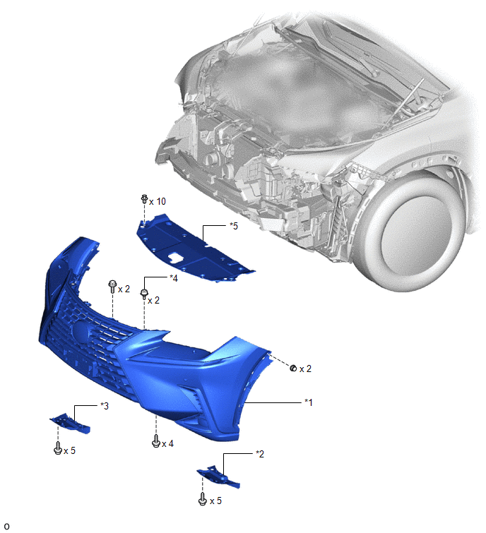
| *1 | FRONT BUMPER ASSEMBLY | *2 | FRONT FENDER FRONT SPLASH SHIELD LH |
| *3 | FRONT FENDER FRONT SPLASH SHIELD RH | *4 | RADIATOR GRILLE PROTECTOR |
| *5 | RADIATOR SUPPORT OPENING COVER | - | - |
ILLUSTRATION
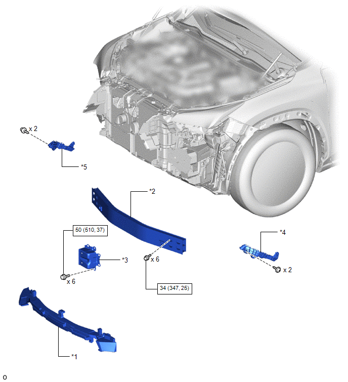
| *1 | FRONT BUMPER ENERGY ABSORBER | *2 | FRONT BUMPER REINFORCEMENT SUB-ASSEMBLY |
| *3 | FRONT BUMPER SIDE MOUNTING BRACKET ASSEMBLY LH | *4 | FRONT BUMPER SIDE RETAINER LH |
| *5 | FRONT BUMPER SIDE RETAINER RH | - | - |
.png) | N*m (kgf*cm, ft.*lbf): Specified torque | - | - |
ILLUSTRATION
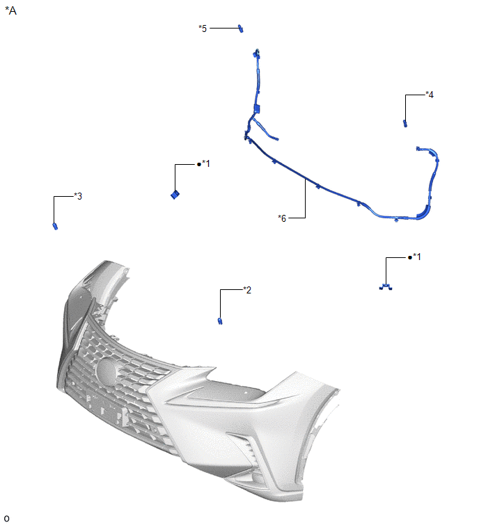
| *A | w/ Headlight Cleaner System | - | - |
| *1 | HEADLIGHT CLEANER WASHER BRACKET | *2 | HEADLIGHT CLEANER WASHER NOZZLE COVER LH |
| *3 | HEADLIGHT CLEANER WASHER NOZZLE COVER RH | *4 | HEADLIGHT WASHER ACTUATOR SUB-ASSEMBLY LH |
| *5 | HEADLIGHT WASHER ACTUATOR SUB-ASSEMBLY RH | *6 | NO. 2 HEADLIGHT CLEANER HOSE |
| ● | Non-reusable part | - | - |
ILLUSTRATION
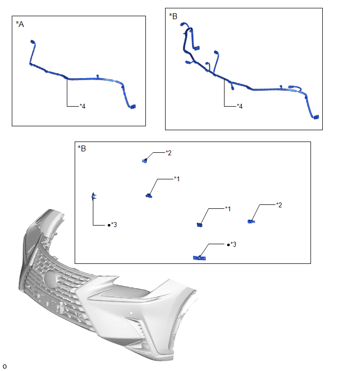
| *A | w/o Intuitive Parking Assist System | *B | w/ Intuitive Parking Assist System |
| *1 | FRONT CENTER ULTRASONIC SENSOR | *2 | FRONT CORNER ULTRASONIC SENSOR |
| *3 | FRONT CORNER ULTRASONIC SENSOR RETAINER | *4 | NO. 3 ENGINE ROOM WIRE |
| ● | Non-reusable part | - | - |
ILLUSTRATION
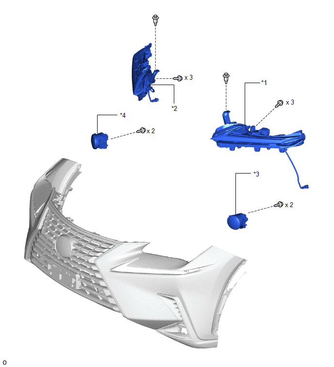
| *1 | CLEARANCE LIGHT ASSEMBLY LH | *2 | CLEARANCE LIGHT ASSEMBLY RH |
| *3 | FOG LIGHT ASSEMBLY LH | *4 | FOG LIGHT ASSEMBLY RH |
ILLUSTRATION
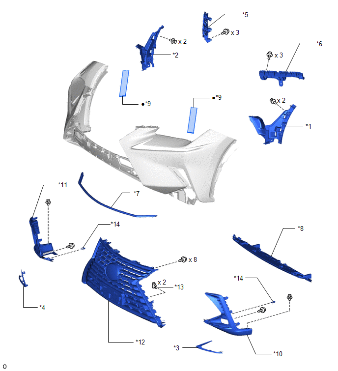
| *1 | AIR INTAKE DUCT LH | *2 | AIR INTAKE DUCT RH |
| *3 | FOG LIGHT BRACKET LH | *4 | FOG LIGHT BRACKET RH |
| *5 | FRONT BUMPER NO. 1 RETAINER BRACKET | *6 | FRONT BUMPER NO. 2 RETAINER BRACKET |
| *7 | HOOD TO FRONT END PANEL SEAL | *8 | LOWER RADIATOR GRILLE |
| *9 | NO. 2 MOULDING TAPE | *10 | NO. 2 RADIATOR GRILLE GARNISH |
| *11 | RADIATOR GRILLE GARNISH | *12 | RADIATOR GRILLE SUB-ASSEMBLY |
| *13 | OUTSIDE MOULDING RETAINER | *14 | RETAINER |
| ● | Non-reusable part | - | - |
READ NEXT:
 Removal
REMOVAL CAUTION / NOTICE / HINT HINT: When the front bumper is damaged or deformed due to an accident or contact with other objects, etc., or the bumper installation area on the body is repaired, it i
Disassembly
DISASSEMBLY PROCEDURE 1. REMOVE HEADLIGHT WASHER ACTUATOR SUB-ASSEMBLY RH (w/ Headlight Cleaner System) Click here 2. REMOVE HEADLIGHT WASHER ACTUATOR SUB-ASSEMBLY LH (w/ Headlight Cleaner System)
Reassembly
REASSEMBLY PROCEDURE 1. INSTALL NO. 2 MOULDING TAPE HINT:
When installing the No. 2 moulding tape, heat the front bumper cover and No. 2 moulding tape using a heat light.
Use the same procedure d
SEE MORE:
Components
COMPONENTS ILLUSTRATION *1 COWL TOP VENTILATOR LOUVER SUB-ASSEMBLY *2 FRONT WIPER ARM HEAD CAP *3 WINDSHIELD WIPER ARM AND BLADE ASSEMBLY LH *4 WINDSHIELD WIPER ARM AND BLADE ASSEMBLY RH N*m (kgf*cm, ft.*lbf): Specified torque - - ILLUSTRATION *1 WINDSHIELD WI
Portable Player cannot be Registered
CAUTION / NOTICE / HINT HINT: Some versions of "Bluetooth" compatible audio players may not function properly, or the functions may be limited using the radio receiver assembly, even if the portable audio player itself can play files. Click here PROCEDURE 1. CHECK THAT PORTABLE PLAYER IS "B
