Lexus NX: Removal
REMOVAL
CAUTION / NOTICE / HINT
HINT:
- Use the same procedure for the RH and LH sides.
- The procedure listed below is for the LH side.
PROCEDURE
1. REMOVE ROOF RACK ASSEMBLY (w/ Roof Rack)
Click here .gif)
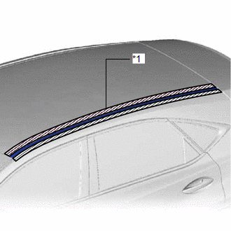
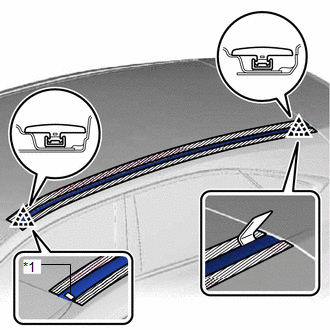
2. REMOVE ROOF DRIP SIDE FINISH MOULDING LH (w/ Roof Rack)
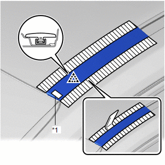
| (a) Put protective tape around the roof drip side finish moulding LH. |
|
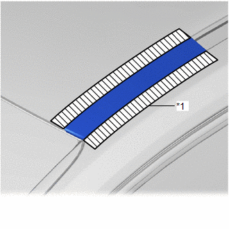
| (b) Using moulding remover D, detach the clip and remove the roof drip side finish moulding LH. |
|
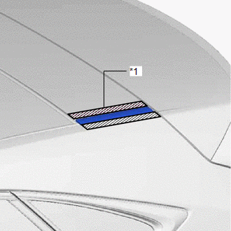
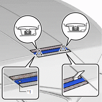
3. REMOVE REAR ROOF DRIP SIDE FINISH MOULDING LH (w/ Roof Rack)
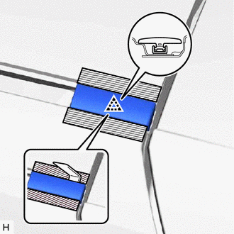
| (a) Put protective tape around the rear roof drip side finish moulding LH. |
|
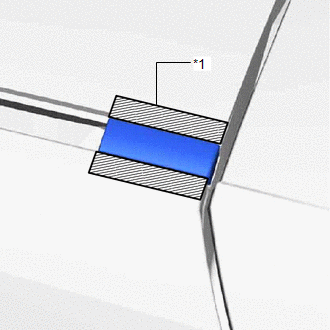
| (b) Using moulding remover D, detach the clip and remove the rear roof drip side finish moulding LH. |
|
4. REMOVE ROOF DRIP SIDE FINISH MOULDING LH (w/o Roof Rack, except Glass Roof)
| (a) Put protective tape around the roof drip side finish moulding LH. |
|
| (b) Using moulding remover D, detach the 2 clips and remove the roof drip side finish moulding LH. |
|
5. REMOVE ROOF DRIP SIDE FINISH MOULDING LH (for Glass Roof)
| (a) Put protective tape around the roof drip side finish moulding LH. |
|
| (b) Using moulding remover D, detach the 2 clips and remove the roof drip side finish moulding LH. |
|
READ NEXT:
 Installation
INSTALLATION CAUTION / NOTICE / HINT HINT:
Use the same procedure for the RH and LH sides.
The procedure listed below is for the LH side.
PROCEDURE 1. INSTALL ROOF DRIP SIDE FINISH MOULDING CL
Removal
REMOVAL CAUTION / NOTICE / HINT HINT:
Use the same procedure for the RH and LH sides.
The procedure listed below is for the LH side.
PROCEDURE 1. REMOVE ROOF HEADLINING ASSEMBLY Click here
SEE MORE:
Initialization
INITIALIZATION NOTICE:
The necessary procedures (adjustment, calibration, initialization or registration) that must be performed after parts are removed and installed, or replaced during headlight ECU sub-assembly LH removal/installation are shown below. Performed Work or System Condition Ne
Installation
INSTALLATION CAUTION / NOTICE / HINT CAUTION: Wear protective gloves. Sharp areas on the parts may injure your hands. PROCEDURE 1. INSTALL SEAT POSITION AIRBAG SENSOR (a) Align the adjustment support and set the seat position airbag sensor into place. *a Adjustment Support
