
Lexus NX: Removal
REMOVAL
CAUTION / NOTICE / HINT
HINT:
- Use the same procedure for the RH and LH sides.
- The procedure described below is for the LH side.
PROCEDURE
1. REMOVE FRONT BUMPER ASSEMBLY
(a) except Sport Package:
Click here .gif)
(b) for Sport Package:
Click here
2. REMOVE HEADLIGHT ASSEMBLY LH
(a) Apply protective tape around the headlight assembly LH.
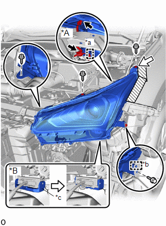
| *A | w/o Headlight ECU |
| *B | w/ Headlight ECU |
| *a | Wire Harness Clamp |
| *b | Guide |
| *c | Connector Lock Lever |
.png) | Protective Tape |
(b) Remove the 3 screws and bolt.
(c) Place your hand at the location indicated by the white arrow shown in the illustration, and disconnect the seat of the screw.
(d) Detach the guide and remove the headlight assembly LH.
(e) w/o Headlight ECU:
Disconnect the 2 connectors and detach the wire harness clamp.
(f) w/ Headlight ECU:
Release the connector lock lever and disconnect the connector.
READ NEXT:
 Disassembly
DISASSEMBLY PROCEDURE 1. PRECAUTION NOTICE:
Be sure to read Precaution thoroughly before servicing.
Click here
Do not reuse parts which have reduced fastening ability due to thread damage.
Wh
Inspection
INSPECTION PROCEDURE 1. INSPECT HEADLIGHT ASSEMBLY LH (a) Apply battery voltage to the connector and check the light illumination condition. OK: Battery Connection Specified Condition Pos
Adjustment
ADJUSTMENT CAUTION / NOTICE / HINT HINT:
Use the same procedure for the RH and LH sides.
The procedure listed below is for the LH side.
It is possible that a headlight assembly is incorrectly i
SEE MORE:
System Description
SYSTEM DESCRIPTION LIN COMMUNICATION SYSTEM DESCRIPTION The LIN communication system is used for communication between the components in the tables below. If communication cannot be performed through LIN communication because of a break in the communication lines or some other reason, the master con
Installation
INSTALLATION PROCEDURE 1. INSTALL AIR CONDITIONING THERMISTOR ASSEMBLY (HUMIDITY SENSOR) *1 Stopper *2 Bracket (a) Attach the 2 brackets, and carefully install the air conditioning thermistor assembly (humidity sensor) to the glass surface, preventing air bubbles from forming between
© 2016-2026 Copyright www.lexunx.com
