Lexus NX: Removal
REMOVAL
CAUTION / NOTICE / HINT
HINT:
- Use the same procedure for the RH and LH sides.
- The procedure described below is for the LH side.
PROCEDURE
1. REMOVE CENTER BACK DOOR GARNISH
Click here .gif)
2. REMOVE BACK DOOR SIDE GARNISH LH
Click here
3. REMOVE BACK DOOR SIDE GARNISH RH
Click here
4. REMOVE BACK DOOR FINISH COVER LH (w/o Power Back Door)
Click here
5. REMOVE BACK DOOR FINISH COVER RH (w/o Power Back Door)
Click here
6. REMOVE BACK DOOR TRIM BASE (w/ Power Back Door)
Click here
7. REMOVE PULL HANDLE (w/ Power Back Door)
Click here
8. REMOVE BACK DOOR LOCK COVER (w/o Power Back Door)
Click here
9. REMOVE BACK DOOR LOCK COVER (w/ Power Back Door)
Click here
10. REMOVE BACK DOOR TRIM BOARD ASSEMBLY
Click here
11. REMOVE BACK DOOR OUTSIDE GARNISH SUB-ASSEMBLY
Click here
12. REMOVE REAR LIGHT ASSEMBLY LH
NOTICE:
If the rear light assembly LH has been removed, replace the rear light gasket with a new one.
(a) Apply protective tape around the rear light assembly LH.
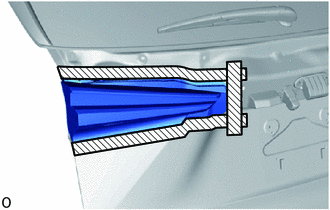
.png) | Protective Tape |
| (b) Disconnect the connector. |
|
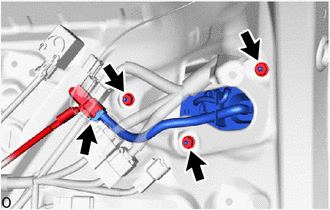
(c) Remove the 3 nuts.
| (d) Remove the bolt. |
|
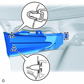
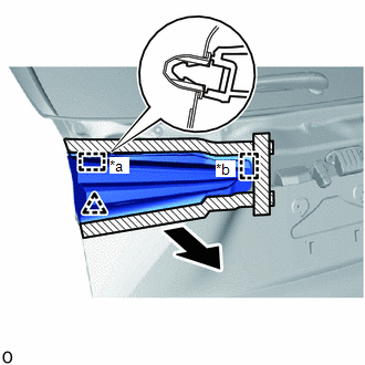
| (e) Detach the guide, pin and clip to remove the rear light assembly LH. |
|
READ NEXT:
 Disassembly
DISASSEMBLY CAUTION / NOTICE / HINT HINT:
Use the same procedure for the RH and LH sides.
The procedure listed below is for the LH side.
PROCEDURE 1. REMOVE REAR LIGHT GASKET LH (a) Remove
Inspection
INSPECTION PROCEDURE 1. INSPECT REAR LIGHT ASSEMBLY LH (a) Apply battery voltage to the connector and check the light illumination condition. OK: Battery Connection Specified Condition Po
Reassembly
REASSEMBLY CAUTION / NOTICE / HINT HINT:
Use the same procedure for the RH and LH sides.
The procedure listed below is for the LH side.
PROCEDURE 1. INSTALL REAR LIGHT SOCKET AND WIRE LH (a) A
SEE MORE:
Removal
REMOVAL CAUTION / NOTICE / HINT HINT: When the front bumper is damaged or deformed due to an accident or contact with other objects, etc., or the bumper installation area on the body is repaired, it is necessary to perform millimeter wave radar sensor adjustment (See page ). PROCEDURE 1. PRECAUTION
Headlight ECU Communication Stop Mode
DESCRIPTION Detection Item Symptom Trouble Area Headlight ECU Communication Stop Mode Any of the following conditions are met:
Communication stop for "Headlight swivel (AFS)" is indicated on the "Communication Bus Check" screen of the Techstream.
Click here
Communication system
