Lexus NX: Components
COMPONENTS
ILLUSTRATION
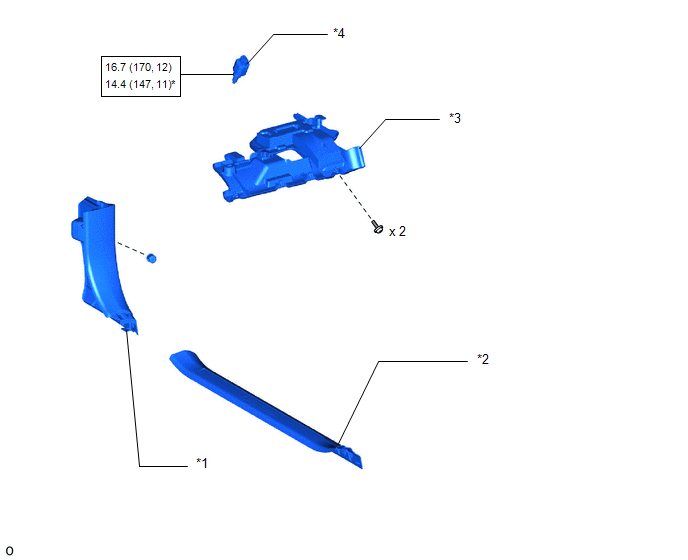
| *1 | COWL SIDE TRIM BOARD LH | *2 | DOOR SCUFF PLATE ASSEMBLY LH |
| *3 | NO. 1 INSTRUMENT PANEL UNDER COVER SUB-ASSEMBLY | *4 | STOP LIGHT SWITCH ASSEMBLY |
| *5 | STOP LIGHT SWITCH MOUNTING ADJUSTER | - | - |
.png) | N*m (kgf*cm, ft.*lbf): Specified torque | * | For use with union nut wrench |
READ NEXT:
 On-vehicle Inspection
ON-VEHICLE INSPECTION PROCEDURE 1. INSPECT STOP LIGHT SWITCH ASSEMBLY (a) Disconnect the stop light switch assembly connector. *a Front view of wire harness connector (to Stop Light
Removal
REMOVAL PROCEDURE 1. REMOVE DOOR SCUFF PLATE ASSEMBLY LH Click here 2. REMOVE COWL SIDE TRIM BOARD LH Click here 3. REMOVE NO. 1 INSTRUMENT PANEL UNDER COVER SUB-ASSEMBLY Click here 4. R
Installation
INSTALLATION PROCEDURE 1. INSTALL STOP LIGHT SWITCH ASSEMBLY (a) Turn the stop light switch assembly in the clockwise direction until it reaches the standard shaft protrusion amount and temporarily
SEE MORE:
Precaution
PRECAUTION CAN COMMUNICATION SYSTEM TROUBLESHOOTING (a) Because the order of diagnosis is important to allow correct diagnosis, make sure to begin troubleshooting using How to Proceed with Troubleshooting when CAN communication system related DTCs are output. Click here (b) Precaution for steerin
Inside rear view mirror
The rear view mirror's position can
be adjusted to enable sufficient
confirmation of the rear view.
Adjusting the height of rear view
mirror
The height of the rear view mirror can
be adjusted to suit your driving posture.
Adjust the height of the rear view mirror
by moving it up and down.
© 2016-2026 Copyright www.lexunx.com
