Lexus NX: Removal
REMOVAL
PROCEDURE
1. REMOVE FRONT WHEEL RH
Click here .gif)
2. REMOVE FRONT FENDER MOULDING SUB-ASSEMBLY RH
HINT:
Use the same procedure described for the LH side.
Click here
3. REMOVE NO. 1 MOULDING TAPE
HINT:
Use the same procedure described for the LH side.
Click here
4. REMOVE NO. 2 MOULDING TAPE
HINT:
Use the same procedure described for the LH side.
Click here
5. REMOVE FRONT FENDER FRONT SPLASH SHIELD RH
HINT:
Use the same procedure described for the LH side.
Click here
6. REMOVE FRONT FENDER LINER RH
Click here
7. DRAIN WINDSHIELD WASHER FLUID
Click here
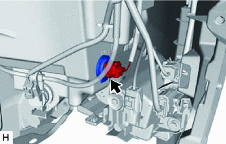
8. REMOVE LEVEL WARNING SWITCH ASSEMBLY
| (a) Disconnect the connector. |
|
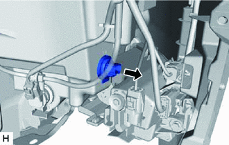
| (b) Remove the level warning switch assembly as shown in the illustration. |
|
READ NEXT:
 Inspection
INSPECTION PROCEDURE 1. INSPECT LEVEL WARNING SWITCH ASSEMBLY *a Component without harness connected (Level Warning Switch Assembly) HINT: The following check should be performed with the lev
Installation
INSTALLATION PROCEDURE 1. INSTALL LEVEL WARNING SWITCH ASSEMBLY (a) Install the level warning switch assembly as shown in the illustration. NOTICE: Make sure that the protrusion of the level warnin
SEE MORE:
Parts Location
PARTS LOCATION ILLUSTRATION *1 REAR HEIGHT CONTROL SENSOR SUB-ASSEMBLY LH *2 BRAKE BOOSTER WITH MASTER CYLINDER ASSEMBLY (SKID CONTROL ECU) *3 HEADLIGHT ASSEMBLY LH - HEADLIGHT ECU SUB-ASSEMBLY LH - HEADLIGHT UNIT ASSEMBLY LH *4 HEADLIGHT ASSEMBLY RH - HEADLIGHT ECU SUB-ASSEMBLY
Precaution
PRECAUTION PRECAUTIONS FOR BLIND SPOT MONITOR SYSTEM (a) The blind spot monitor function may not detect vehicles correctly in the following conditions: (1) When the sensor is misaligned due to a strong impact to the sensor or its surrounding area. (2) When mud, snow, ice, a sticker, etc. is covering
© 2016-2026 Copyright www.lexunx.com
