Lexus NX: Removal
REMOVAL
PROCEDURE
1. REMOVE NO. 3 DECK BOARD SUB-ASSEMBLY
Click here .gif)
2. REMOVE REAR DECK FLOOR BOX
Click here
3. REMOVE DECK FLOOR BOX LH
Click here
4. PRECAUTION
CAUTION:
Be sure to read Precaution thoroughly before servicing.
Click here
NOTICE:
-
After the power switch is turned off, there may be a waiting time before disconnecting the negative (-) auxiliary battery terminal.
Click here
-
When removing front seat assembly RH, perform zero point calibration and sensitivity check.
Click here
-
When replacing the occupant detection ECU, perform zero point calibration and sensitivity check.
Click here
5. DISCONNECT CABLE FROM NEGATIVE AUXILIARY BATTERY TERMINAL
CAUTION:
Wait at least 90 seconds after disconnecting the cable from the negative (-) auxiliary battery terminal to disable the SRS system.
(a) Loosen the nut and disconnect the cable from the negative (-) auxiliary battery terminal.
6. REMOVE FRONT SEAT ASSEMBLY RH
Click here
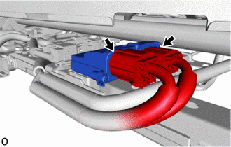
7. REMOVE OCCUPANT DETECTION ECU
| (a) Disconnect the 2 connectors. |
|
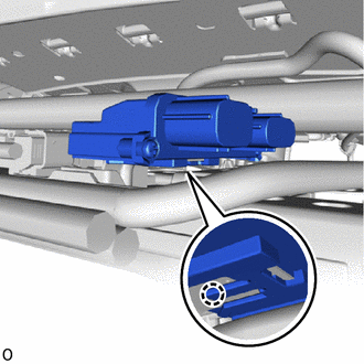
| (b) Detach the claw and remove the occupant detection ECU. |
|
READ NEXT:
 Installation
INSTALLATION PROCEDURE 1. INSTALL OCCUPANT DETECTION ECU (a) Attach the claw to install the occupant detection ECU. NOTICE: If the occupant detection ECU has been dropped, or there are any cracks, den
Precaution
PRECAUTION PRECAUTION FOR DISCONNECTING CABLE FROM NEGATIVE AUXILIARY BATTERY TERMINAL NOTICE:
After turning the power switch off, waiting time may be required before disconnecting the cable from t
SEE MORE:
Installation
INSTALLATION PROCEDURE 1. INSTALL POWER STEERING ECU ASSEMBLY (a) Install a new electric power steering motor shaft damper to the power steering ECU assembly. (b) Install a new electric power steering motor shaft spacer to the power steering ECU assembly. (c) Temporarily install the power steerin
Components
COMPONENTS ILLUSTRATION *A for Sport Package - - *1 BACK DOOR NAME PLATE *2 BACK DOOR NO. 2 NAME PLATE *3 REAR BODY NO. 4 NAME PLATE *4 SYMBOL EMBLEM ● Non-reusable part - - ILLUSTRATION *A for Sport Package - - *1 FRONT FENDER NO. 1 NAME
© 2016-2026 Copyright www.lexunx.com
