Lexus NX: Removal
REMOVAL
PROCEDURE
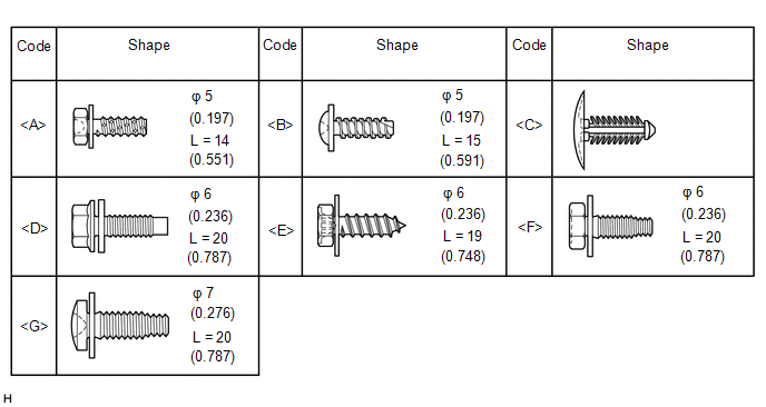
1. TABLE OF BOLT, SCREW AND CLIP
HINT:
All bolts, screws, and clips relevant to installing and removing the instrument panel are shown along with their alphabet code in the table below.
2. DISABLE AUTOAWAY/RETURN FUNCTION (for Power Tilt and Power Telescopic Steering Column)
(a) Disable the autoaway/return function by changing the customize parameter.
Click here .gif)
CAUTION:
Record the current customize parameter setting (whether the autoaway/return function is enabled or disabled) in order to restore the current setting after finishing the operation.
HINT:
Performing the above operation causes the autoaway/return function to be disabled when the power switch is turned off.
(b) Turn the power switch on (IG). Operate the tilt and telescopic switch to fully extend and lower the steering column assembly.
(c) Turn the power switch off.
3. REMOVE NO. 3 DECK BOARD SUB-ASSEMBLY
Click here
4. REMOVE REAR DECK FLOOR BOX
Click here
5. REMOVE DECK FLOOR BOX LH
Click here
6. PRECAUTION
CAUTION:
Be sure to read Precaution thoroughly before serving.
Click here
NOTICE:
After turning the power switch off, there may be a waiting time before disconnecting the negative (-) auxiliary battery terminal.
Click here
7. DISCONNECT CABLE FROM NEGATIVE AUXILIARY BATTERY TERMINAL
CAUTION:
- Wait at least 90 seconds after disconnecting the cable from the negative (-) auxiliary battery terminal to disable the SRS system.
- If the airbag deploys for any reason. it may cause a serious accident.
8. REMOVE HEADLIGHT DIMMER SWITCH ASSEMBLY
Click here
9. REMOVE UPPER INSTRUMENT PANEL SUB-ASSEMBLY
Click here
10. REMOVE CONSOLE BOX ASSEMBLY
Click here
11. REMOVE AIR CONDITIONING CONTROL ASSEMBLY
| (a) Pull the air conditioning control assembly in the direction indicated by the arrows shown in the illustration to detach the 6 clips. |
|
(b) Disconnect the connectors and remove the air conditioning control assembly.
12. REMOVE CENTER INSTRUMENT PANEL REGISTER ASSEMBLY
| (a) Place your hand as shown in the illustration, and then pull the center instrument panel register assembly in the direction indicated by the arrow shown in the illustration to detach the 4 clips and remove the center instrument panel register assembly. |
|
13. REMOVE CENTER HEATER TO REGISTER DUCT
| (a) Remove the 2 clips <C>. |
|
(b) Detach the 2 claws and remove the center heater to register duct.
14. REMOVE RADIO RECEIVER ASSEMBLY WITH BRACKET
Click here
15. REMOVE NO. 2 INSTRUMENT PANEL UNDER COVER SUB-ASSEMBLY
| (a) Using moulding remover A, detach the 3 claws and guide. |
|
(b) Disconnect the connector and remove the No. 2 instrument panel under cover sub-assembly.
16. REMOVE DOOR SCUFF PLATE ASSEMBLY LH
Click here
17. REMOVE DOOR SCUFF PLATE ASSEMBLY RH
Click here
18. REMOVE COWL SIDE TRIM BOARD LH
Click here
19. REMOVE COWL SIDE TRIM BOARD RH
Click here
20. REMOVE LOWER NO. 1 INSTRUMENT PANEL AIRBAG ASSEMBLY
Click here
21. REMOVE DCM (TELEMATICS TRANSCEIVER) WITH BRACKET
Click here
22. REMOVE NO. 1 SPEAKER ASSEMBLY WITH BOX
Click here
23. REMOVE GLOVE COMPARTMENT DOOR STOPPER SUB-ASSEMBLY
| (a) Detach the claw and remove the glove compartment door stopper sub-assembly. |
|
24. REMOVE LOWER INSTRUMENT PANEL SUB-ASSEMBLY
(a) Detach the clamps.
(b) Remove the 2 bolts <D>.
(c) Remove the 8 screws <F> or <G>.
(d) Remove the screw <E>.
(e) Disconnect the connector and room temperature sensor.
(f) Detach the 2 claws and disconnect the DLC3.
(g) Detach the claw and 2 guides and disconnect the hood lock control lever sub-assembly and remove the lower instrument panel sub-assembly.
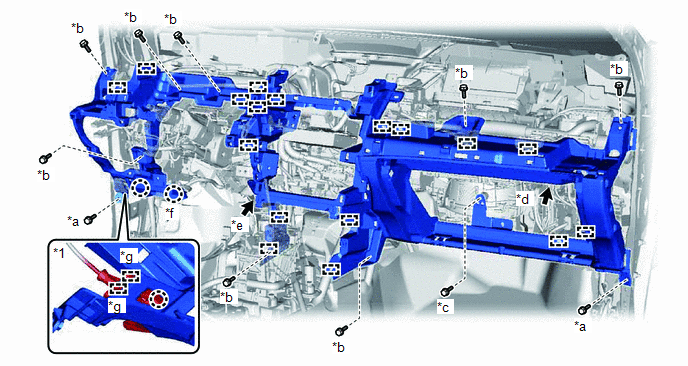
| *1 | Hood Lock Control Lever Sub-assembly | - | - |
| *a | Bolt <D> | *b | Screw <F> or <G> |
| *c | Screw <E> | *d | Connector |
| *e | Room Temperature Sensor | *f | DLC3 |
| *g | Guide | - | - |
READ NEXT:
 Disassembly
DISASSEMBLY PROCEDURE 1. REMOVE GLOVE COMPARTMENT DOOR CHECK CUSHION HINT: Use the same procedure for both glove compartment door check cushions. (a) Using a screwdriver, detach the 3 claws and rem
Reassembly
REASSEMBLY PROCEDURE 1. INSTALL GLOVE COMPARTMENT DOOR LOCK CYLINDER ASSEMBLY (a) With the cylinder lock pressed, insert the glove compartment door lock cylinder assembly into the glove compartment do
Installation
INSTALLATION CAUTION / NOTICE / HINT HINT: A bolt without a torque specification is shown in the standard bolt chart. Click here PROCEDURE 1. INSTALL LOWER INSTRUMENT PANEL SUB-ASSEMBLY (a) Cut off
SEE MORE:
Dtc Check / Clear
DTC CHECK / CLEAR DTC CHECK/CLEAR (a) Check for DTCs. (1) Connect the Techstream to the DLC3. (2) Turn the power switch on (IG). (3) Turn the Techstream on. (4) Read the DTCs following the prompts on the Techstream screen. Enter the following menus: Chassis / ABS/VSC/TRAC / Trouble Codes. Chassis &g
Brake Control Warning Light does not Come ON
DESCRIPTION The skid control ECU (brake booster with master cylinder assembly) is connected to the combination meter assembly via CAN communication. CAUTION / NOTICE / HINT NOTICE: When replacing the skid control ECU (brake booster with master cylinder assembly), perform initialization and calibrati
