Lexus NX: Removal
REMOVAL
PROCEDURE
1. REMOVE REAR SEAT ASSEMBLY (for Manual Seat)
Click here .gif)
2. REMOVE REAR SEAT ASSEMBLY (for Power Seat)
Click here
3. REMOVE TONNEAU COVER ASSEMBLY
Click here
4. REMOVE DECK BOARD ASSEMBLY
Click here
5. REMOVE NO. 2 DECK BOARD SUB-ASSEMBLY
Click here
6. REMOVE NO. 3 DECK BOARD SUB-ASSEMBLY
Click here
7. REMOVE REAR DECK FLOOR BOX
Click here
8. REMOVE SPARE TIRE
Click here
9. REMOVE DECK FLOOR BOX LH
Click here
10. REMOVE DECK FLOOR BOX RH
Click here
11. REMOVE NO. 1 TOOL BOX SUB-ASSEMBLY
Click here
12. REMOVE NO. 2 TOOL BOX SUB-ASSEMBLY
Click here
13. REMOVE REAR FLOOR FINISH PLATE
Click here
14. REMOVE REAR DOOR SCUFF PLATE RH
Click here
15. REMOVE REAR DOOR OPENING TRIM WEATHERSTRIP RH
Click here
16. REMOVE UPPER DECK TRIM SIDE BOARD RH
Click here
17. REMOVE ROPE HOOK ASSEMBLY
Click here
18. REMOVE LUGGAGE HOLD BELT STRIKER ASSEMBLY
Click here
19. REMOVE NO. 1 LUGGAGE COMPARTMENT TRIM HOOK
Click here
20. REMOVE DECK TRIM SIDE PANEL ASSEMBLY RH
Click here
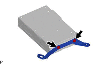
21. REMOVE STEREO COMPONENT AMPLIFIER ASSEMBLY WITH BRACKET
(a) for 10 Speakers:
(1) Detach the claw and remove the connector lock as shown in the illustration.
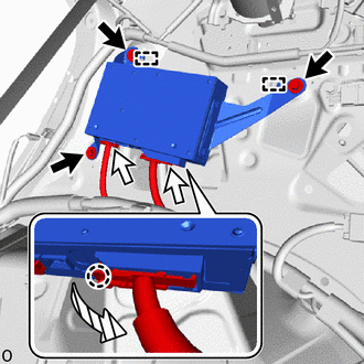
 | Bolt |
 | Connector |
 | Direction to unlock |
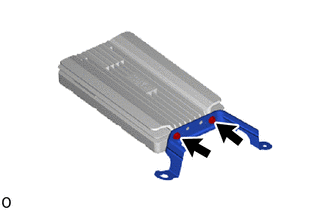
(2) Disconnect the 2 connectors.
(3) Remove the 3 bolts, detach the guide and stereo component amplifier assembly with bracket.
(b) for 14 Speakers:
(1) Detach the claw and remove the connector lock as shown in the illustration.
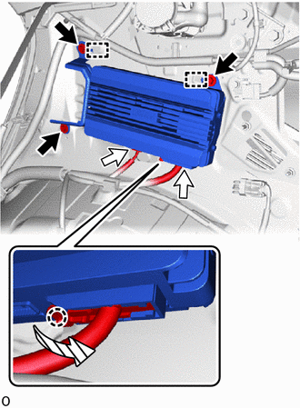
| | Bolt |
| | Connector |
| | Direction to unlock |
(2) Disconnect the connectors.
(3) Remove the 3 bolts, detach the guide and stereo component amplifier assembly with bracket.
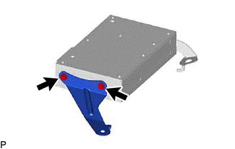
22. REMOVE NO. 1 AMPLIFIER BRACKET
| (a) for 10 Speakers: (1) Remove the 2 screws and No. 1 amplifier bracket. |
|
| (b) for 14 Speakers: (1) Remove the 2 screws and No. 1 amplifier bracket. |
|
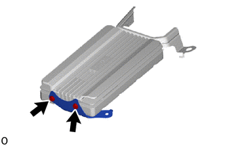
23. REMOVE NO. 2 AMPLIFIER BRACKET
| (a) for 10 Speakers: (1) Remove the 2 screws and No. 2 amplifier bracket. |
|
| (b) for 14 Speakers: (1) Remove the 2 screws and No. 2 amplifier bracket. |
|
24. REMOVE STEREO COMPONENT AMPLIFIER ASSEMBLY
READ NEXT:
 Installation
INSTALLATION CAUTION / NOTICE / HINT HINT: A bolt without a torque specification is shown in the standard bolt chart. Click here PROCEDURE 1. INSTALL STEREO COMPONENT AMPLIFIER ASSEMBLY 2. INSTALL N
Stereo Jack Adapter Assembly
ComponentsCOMPONENTS ILLUSTRATION *A w/ Navigation System - - *1 NO. 1 STEREO JACK ADAPTER ASSEMBLY *2 NO. 3 BOX PANEL ILLUSTRATION *A w/o Navigation System - - *
Window Glass Antenna Wire
On-vehicle InspectionON-VEHICLE INSPECTION PROCEDURE 1. INSPECT WINDOW GLASS ANTENNA WIRE (a) Check for continuity of the antenna. HINT: Check for continuity at the center of each antenna wire as
SEE MORE:
Terminals Of Ecu
TERMINALS OF ECU CHECK COMBINATION METER ASSEMBLY (a) Disconnect the I10 combination meter assembly connector. (b) Measure the resistance and voltage according to the value(s) in the table below. Tester Connection Wiring Color Terminal Description Condition Specified Condition I10-21
Problem Symptoms Table
PROBLEM SYMPTOMS TABLE NOTICE: If the main body ECU (multiplex network body ECU) is replaced, refer to the Smart Access System with Push-button Start (for Entry Function). Click here HINT:
Use the table below to help determine the cause of problem symptoms. If multiple suspected areas are list
