Lexus NX: Television Camera (for Front)
Components
COMPONENTS
ILLUSTRATION
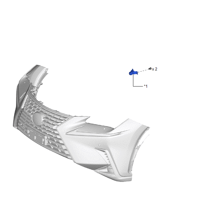
| *1 | FRONT TELEVISION CAMERA ASSEMBLY | - | - |
Removal
REMOVAL
PROCEDURE
1. PRECAUTION
Click here .gif)
2. REMOVE FRONT BUMPER COVER
(a) for Sport Package:
Click here
(b) except Sport Package:
Click here
3. REMOVE FRONT TELEVISION CAMERA ASSEMBLY
| (a) Disconnect the connector. |
|
(b) Remove the 2 screws and front television camera assembly.
Installation
INSTALLATION
PROCEDURE
1. INSTALL FRONT TELEVISION CAMERA ASSEMBLY
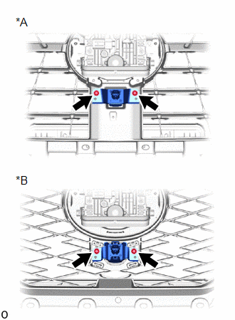
(a) Align the 2 positioning ribs of the front television camera assembly to set it.
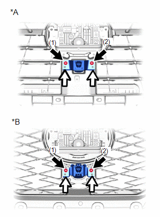
| *A | except Sport Package |
| *B | for Sport Package |
.png) | Screw |
.png) | Positioning Rib |
(b) Install the 2 screws in the order shown in the illustration.
(c) Connect the connector.
2. INSTALL FRONT BUMPER COVER
(a) except Sport Package:
Click here .gif)
(b) for Sport Package:
Click here
3. ADJUST FRONT TELEVISION CAMERA ASSEMBLY
Click here
4. PERFORM CALIBRATION
Click here
READ NEXT:
 Components
COMPONENTS ILLUSTRATION *A w/ Woofer *B w/o Woofer *C w/o Power Back Door *D w/ Power Back Door *1 BACK DOOR CENTER GARNISH *2 BACK DOOR FINISH COVER LH *3 BACK DOO
Removal
REMOVAL PROCEDURE 1. PRECAUTION (a) w/ Parking Assist Monitor System: Click here (b) w/ Panoramic View Monitor System: Click here 2. REMOVE BACK DOOR TRIM BASE (w/ Power Back Door) Click here 3.
SEE MORE:
Horn Circuit
DESCRIPTION When the theft deterrent system is switched from the armed state to the alarm sounding state, the main body ECU (multiplex network body ECU) transmits a signal to cause the horn to sound at intervals of 0.4 seconds. WIRING DIAGRAM CAUTION / NOTICE / HINT NOTICE: Inspect the fuses for ci
EPB High Temperature (C13AA)
DESCRIPTION If the electric parking brake is used continuously, the parking brake actuator assembly overheat prevention stops the system. This DTC is stored to protect the system and is not a malfunction. DTC No. Detection Item DTC Detection Condition Trouble Area Memory Note C13AA
