Lexus NX: Removal
REMOVAL
PROCEDURE
1. PRECAUTION
Click here .gif)
2. REMOVE FRONT BUMPER COVER
(a) for Sport Pacakge:
Click here
(b) except Sport Pacakge:
Click here
3. REMOVE NO. 3 ENGINE ROOM WIRE
(a) for Sport Pacakge:
Click here
(b) except Sport Pacakge:
Click here
4. REMOVE FRONT CORNER ULTRASONIC SENSOR
| (a) Detach the 2 claws and remove the front corner ultrasonic sensor. HINT:
|
|
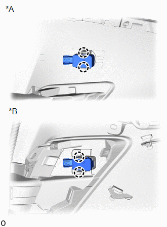
5. REMOVE FRONT CENTER ULTRASONIC SENSOR
| (a) Detach the 2 claws and remove the front center ultrasonic sensor. HINT:
|
|
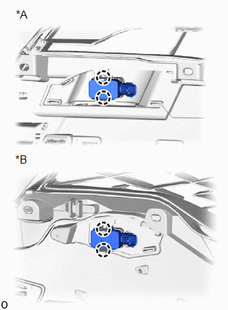
6. REMOVE FRONT CORNER ULTRASONIC SENSOR RETAINER (except Sport Package)
HINT:
- When removing the front corner ultrasonic sensor retainer, heat the front bumper assembly and front corner ultrasonic sensor retainer using a heat light.
- Use the same procedure for both front corner ultrasonic sensor retainers.
Standard:
| Item | Temperature |
|---|---|
| Front Bumper Assembly | 20 to 30°C (68 to 86°F) |
| Front Corner Ultrasonic Sensor Retainer |
NOTICE:
- Do not heat the front bumper assembly on front corner ultrasonic sensor retainer excessirely.
- Do not reuse the removed front corner ultrasonic sensor retainer.
| (a) Remove the front corner ultrasonic sensor retainer. |
|
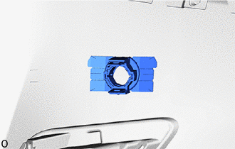
7. REMOVE ULTRASONIC SENSOR CUSHION SET
HINT:
Perform the following procedure only when replacement of a ultrasonic sensor cushion set is necessary.
(a) Remove the ultrasonic sensor cushion set as shown in the illustration.
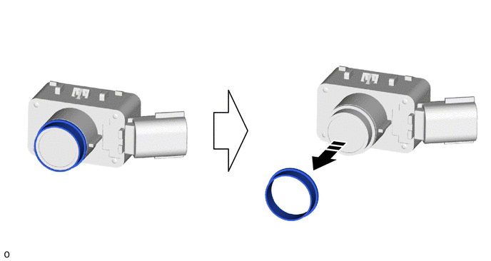
 | Remove in this Direction | - | - |
READ NEXT:
 Inspection
INSPECTION PROCEDURE 1. INSPECT FRONT CENTER ULTRASONIC SENSOR (a) Measure the resistance according to the value(s) in the table below. Standard Resistance: Tester Connection Condition Spec
Installation
INSTALLATION PROCEDURE 1. INSTALL ULTRASONIC SENSOR CUSHION SET HINT: Perform the following procedure only when replacement of a ultrasonic sensor cushion set is necessary. (a) Install the ultrasonic
SEE MORE:
Precaution
PRECAUTION PRECAUTIONS DURING REPLACEMENT NOTICE: When replacing electronic parts, if there is a possibility that your body may contact a circuit board, etc., use the recommended tools and observe all precautions to prevent damage to the system by electrostatic discharge (ESD). (a) Procedures where
Disposal
DISPOSAL PROCEDURE 1. DISPOSE OF BRAKE BOOSTER PUMP ASSEMBLY (a) Remove the accumulator from the brake booster pump assembly. (b) Secure the accumulator in a vise. (c) Using a hacksaw, make a cut in the side of the accumulator within location (A) to release the high-pressure gas. Location Le
