Lexus NX: Removal
REMOVAL
CAUTION / NOTICE / HINT
HINT:
- Use the same procedure for the RH and LH sides.
- The following procedure is for the LH side.
NOTICE:
- When the brake pedal is first depressed after replacing the brake pads or pushing back the disc brake piston, DTC C1214 may be output. As there is no malfunction, clear the DTCs.
- While the auxiliary battery is connected, even if the power switch is off, the brake control system activates when the brake pedal is depressed or the door courtesy switch is turned on. Therefore, even if only brake pads are to be removed and installed, be sure to perform the Disable Brake Control procedure and disconnect the cable from the negative (-) terminal of the auxiliary battery before beginning work.
PROCEDURE
1. PRECAUTION
NOTICE:
After turning the power switch off, there may be a waiting time before disconnecting the negative (-) auxiliary battery terminal.
Click here 
2. REMOVE NO. 3 DECK BOARD SUB-ASSEMBLY
Click here
3. REMOVE REAR DECK FLOOR BOX
Click here
4. REMOVE DECK FLOOR BOX LH
Click here
5. DISABLE BRAKE CONTROL
Click here
6. REMOVE FRONT WHEEL
Click here
7. DRAIN BRAKE FLUID
NOTICE:
Wash off brake fluid immediately if it comes in contact with any painted surface.
8. DISCONNECT FRONT FLEXIBLE HOSE
| (a) Remove the union bolt and gasket. |
|
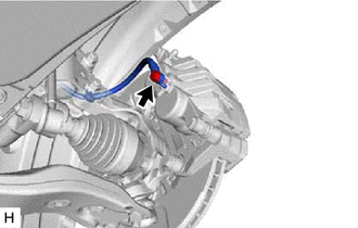
(b) Disconnect the flexible hose from the disc brake cylinder assembly LH.
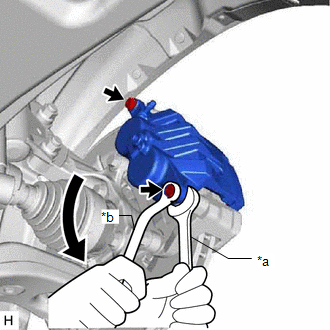
9. REMOVE DISC BRAKE CYLINDER ASSEMBLY LH
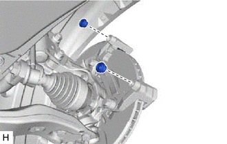
| (a) Hold the front disc brake cylinder slide pin and remove the 2 bolts and disc brake cylinder assembly LH. NOTICE: Remove the disc brake cylinder assembly while holding both of the brake pads because the anti-squeal springs may fall off the brake pads. |
|
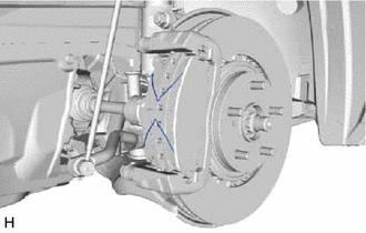
10. REMOVE FRONT DISC BRAKE PAD
| (a) Remove the 2 anti-squeal springs. |
|
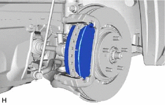
| (b) Remove the 2 front disc brake pads from the front disc brake cylinder mounting LH. |
|
11. REMOVE FRONT ANTI-SQUEAL SHIM KIT
(a) Remove the 2 No. 1 anti-squeal shims from the front disc brake pads.
12. REMOVE NO. 1 PAD WEAR INDICATOR PLATE
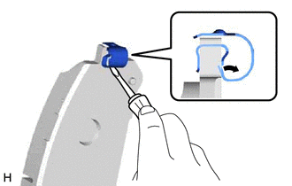
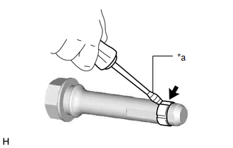
| (a) Using a screwdriver, remove the No. 1 pad wear indicator plates from the front disc brake pads as shown in the illustration. |
|
13. REMOVE FRONT NO. 1 DISC BRAKE PAD SUPPORT PLATE
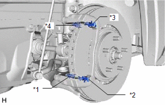
| (a) Remove the 4 front disc brake pad support plates from the front disc brake cylinder mounting LH. NOTICE: Each front disc brake pad support plate has a different shape. Be sure to put an identification mark on each front disc brake pad support plate so that they can be reinstalled to their original position. |
|
14. REMOVE FRONT NO. 2 DISC BRAKE PAD SUPPORT PLATE
15. REMOVE FRONT NO. 3 DISC BRAKE PAD SUPPORT PLATE
16. REMOVE FRONT NO. 4 DISC BRAKE PAD SUPPORT PLATE
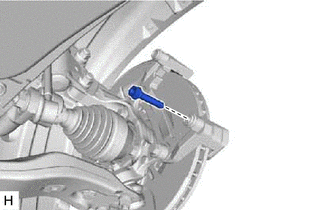
17. REMOVE NO. 2 DISC BRAKE CYLINDER SLIDE PIN
| (a) Remove the No. 2 disc brake cylinder slide pin from the front disc brake cylinder mounting LH. |
|
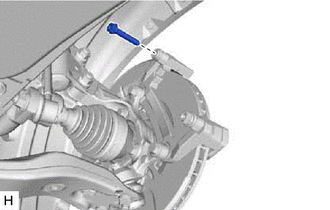
18. REMOVE FRONT DISC BRAKE CYLINDER SLIDE PIN
| (a) Remove the front disc brake cylinder slide pin from the front disc brake cylinder mounting LH. |
|
19. REMOVE FRONT DISC BRAKE CYLINDER SLIDE BUSH
| (a) Using a screwdriver with its tip wrapped with protective tape, remove the front disc brake cylinder slide bush from the No. 2 disc brake cylinder slide pin. HINT: Tape the screwdriver tip before use. NOTICE: Do not damage the No. 2 disc brake cylinder slide pin. |
|
20. REMOVE FRONT DISC BRAKE BUSH DUST BOOT
| (a) Remove the 2 front disc brake bush dust boots from the front disc brake cylinder mounting LH. |
|
21. REMOVE FRONT DISC BRAKE CYLINDER MOUNTING LH
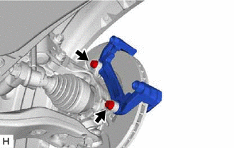
| (a) Remove the 2 bolts and front disc brake cylinder mounting LH from the steering knuckle. |
|
22. REMOVE FRONT DISC
| (a) Put matchmarks on the front disc and axle hub. |
|
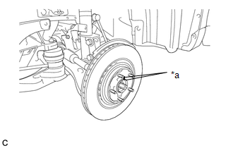
(b) Remove the front disc.
READ NEXT:
 Disassembly
DISASSEMBLY CAUTION / NOTICE / HINT HINT:
Use the same procedure for the RH and LH sides.
The following procedure is for the LH side.
PROCEDURE 1. REMOVE FRONT DISC BRAKE PISTON (a) Place a
Inspection
INSPECTION PROCEDURE 1. CHECK BRAKE CYLINDER AND PISTON (a) Check the cylinder bore and piston for rust or scoring. If necessary, replace the brake cylinder and piston. 2. CHECK PAD LINING THICKNESS (
Reassembly
REASSEMBLY CAUTION / NOTICE / HINT HINT:
Use the same procedure for the RH and LH sides.
The following procedure is for the LH side.
PROCEDURE 1. TEMPORARILY INSTALL FRONT DISC BRAKE BLEEDER P
SEE MORE:
Invalid Data Received from HVAC Control Module (U0424-537)
DESCRIPTION If there is a malfunction in the air conditioning amplifier assembly, DTC U0424-537 will be stored. DTC No. Detection Item DTC Detection Condition Trouble Area MIL Warning Indicate U0424-537 Invalid Data Received from HVAC Control Module Air conditioning amplifier as
ECU Power Source Circuit Malfunction (B2620)
DESCRIPTION The ECU power source circuit supplies positive (+) voltage to the multiplex tilt and telescopic ECU. DTC No. Detection Item DTC Detection Condition Trouble Area B2620 ECU Power Source Circuit Malfunction The voltage of the ECU power source drops to 8 V or less and this c
