Lexus NX: Disassembly
DISASSEMBLY
CAUTION / NOTICE / HINT
HINT:
- Use the same procedure for the RH and LH sides.
- The following procedure is for the LH side.
PROCEDURE
1. REMOVE FRONT DISC BRAKE PISTON
| (a) Place a piece of cloth between the front disc brake pistons and the disc brake cylinder assembly LH. |
|
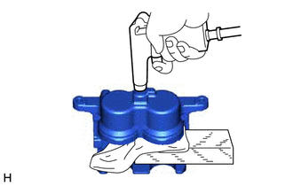
(b) Using compressed air, remove one of the disc brake pistons from the front disc brake cylinder assembly LH.
CAUTION:
Do not place your fingers in front of the front disc brake piston when using compressed air.
NOTICE:
Be careful not to spatter the brake fluid.
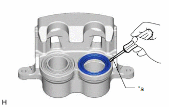
2. REMOVE CYLINDER BOOT
| (a) Using a screwdriver with its tip wrapped with protective tape, remove the 2 cylinder boots from the disc brake cylinder assembly LH. HINT: Tape the screwdriver tip before use. NOTICE: Be careful not to damage the disc brake cylinder assembly LH. |
|
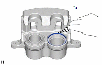
3. REMOVE PISTON SEAL
| (a) Using a screwdriver with its tip wrapped with protective tape, remove the 2 piston seals from the disc brake cylinder assembly LH. HINT: Tape the screwdriver tip before use. NOTICE: Be careful not to damage the inner cylinder and piston seal groove. |
|
4. REMOVE FRONT DISC BRAKE BLEEDER PLUG CAP
5. REMOVE FRONT DISC BRAKE BLEEDER PLUG
READ NEXT:
 Inspection
INSPECTION PROCEDURE 1. CHECK BRAKE CYLINDER AND PISTON (a) Check the cylinder bore and piston for rust or scoring. If necessary, replace the brake cylinder and piston. 2. CHECK PAD LINING THICKNESS (
Reassembly
REASSEMBLY CAUTION / NOTICE / HINT HINT:
Use the same procedure for the RH and LH sides.
The following procedure is for the LH side.
PROCEDURE 1. TEMPORARILY INSTALL FRONT DISC BRAKE BLEEDER P
Installation
INSTALLATION CAUTION / NOTICE / HINT HINT:
Use the same procedure for the RH and LH sides.
The following procedure is for the LH side.
NOTICE: When the brake pedal is first depressed after rep
SEE MORE:
Parts Location
PARTS LOCATION ILLUSTRATION *1 INNER REAR VIEW MIRROR ASSEMBLY - GARAGE DOOR OPENER *2 INSTRUMENT PANEL JUNCTION BLOCK ASSEMBLY - ECU-IG NO. 3 FUSE *3 NO.1 ENGINE ROOM JUNCTION BLOCK ASSEMBLY - ECU-B NO. 1 FUSE - -
Work Procedure
WORK PROCEDURE PROCEDURES NECESSARY WHEN ECU OR OTHER PARTS ARE REPLACED Replacement Part Necessary Procedure Effect/Inoperative Function when Necessary Procedures are not Performed Link
*1: w/ SXM System
*2: The vehicle height changes because of suspension or tire replacement *3: w/ Ha
