Lexus NX: Rear Door Courtesy Switch Circuit
DESCRIPTION
The fold seat control ECU receives the switch operation signal, driving condition signal and rear door open/close signal. Then the fold seat control ECU actives the rear seat according to these signals.
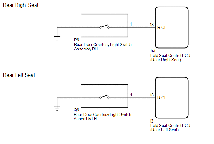
WIRING DIAGRAM
PROCEDURE
| 1. | INSPECT REAR DOOR COURTESY LIGHT SWITCH ASSEMBLY |
(a) Remove the rear door courtesy light switch assembly.
Click here .gif)
(b) Inspect the rear door courtesy light switch assembly.
Click here
| NG | .gif) | REPLACE REAR DOOR COURTESY LIGHT SWITCH ASSEMBLY |
|
.gif)
| 2. | CHECK HARNESS AND CONNECTOR (FOLD SEAT CONTROL ECU - REAR DOOR COURTESY LIGHT SWITCH ASSEMBLY) |
(a) Rear Right Seat:
(1) Disconnect the h3 fold seat control ECU (rear right seat) connector.
(2) Disconnect the P6 rear door courtesy light switch assembly RH connector.
(b) Rear Left Seat:
(1) Disconnect the i3 fold seat control ECU (rear left seat) connector.
(2) Disconnect the Q6 rear door courtesy light switch assembly LH connector.
(c) Measure the resistance according to the value(s) in the table below.
Standard Resistance:
Rear Right Seat
| Tester Connection | Condition | Specified Condition |
|---|---|---|
| h3-18 (R CL) - P6-1 | Always | Below 1 Ω |
| h3-18 (R CL) or P6-1 - Body ground | Always | 10 kΩ or higher |
Rear Left Seat
| Tester Connection | Condition | Specified Condition |
|---|---|---|
| i3-18 (R CL) - Q6-1 | Always | Below 1 Ω |
| i3-18 (R CL) or Q6-1 - Body ground | Always | 10 kΩ or higher |
| OK | | PROCEED TO NEXT SUSPECTED AREA SHOWN IN PROBLEM SYMPTOMS TABLE |
| NG | | REPAIR OR REPLACE HARNESS OR CONNECTOR |
READ NEXT:
 Back Door Courtesy Switch Circuit
DESCRIPTION The fold seat control ECU receives the switch operation signal, driving condition signal and back door open/close signal from the back door lock assembly. The fold seat control ECU actives
Fold Seat Switch Circuit
DESCRIPTION When the fold seat switch is operated, a switch operation signal is sent to the fold seat control ECU. The ECU receives switch operation signals from each switch and activates the reclinin
Folding Motor Circuit
DESCRIPTION The fold seat control ECU receives switch operation signals from the No. 1 and No. 2 fold seat switches and activates the power seat motors. At this time, the Hall IC detects the actuation
SEE MORE:
Components
COMPONENTS ILLUSTRATION *1 DECK FLOOR BOX LH *2 NO. 3 DECK BOARD SUB-ASSEMBLY *3 REAR DECK FLOOR BOX *4 NEGATIVE AUXILIARY BATTERY TERMINAL N*m (kgf*cm, ft.*lbf): Specified torque - - ILLUSTRATION *1 AIR CONDITIONING CONTROL ASSEMBLY *2 CENTER HEATER TO RE
Panel Switches do not Function
CAUTION / NOTICE / HINT NOTICE: When replacing the radio receiver assembly, always replace it with a new one. If a radio receiver assembly which was installed to another vehicle is used, the following may occur:
A communication malfunction DTC may be stored.
The radio receiver assembly may not
