Lexus NX: Removal
REMOVAL
CAUTION / NOTICE / HINT
HINT:
- Use the same procedure for the RH and LH sides.
- The following procedure is for the LH side.
NOTICE:
- When the brake pedal is first depressed after replacing the brake pads or pushing back the disc brake piston, DTC C1214 may be output. As there is no malfunction, clear the DTCs.
- While the auxiliary battery is connected, even if the power switch is off, the brake control system activates when the brake pedal is depressed or the door courtesy switch is turned on. Therefore, even if only brake pads are to be removed and installed, be sure to perform the Disable Brake Control procedure and disconnect the cable from the negative (-) terminal of the auxiliary battery before beginning work.
PROCEDURE
1. REMOVE NO. 3 DECK BOARD SUB-ASSEMBLY
Click here .gif)
2. REMOVE REAR DECK FLOOR BOX
Click here
3. REMOVE DECK FLOOR BOX LH
Click here
4. REAR BRAKE PAD REPLACEMENT MODE
Click here
5. PRECAUTION
CAUTION:
Be sure to read Precoution thoroughly before serving.
Click here
NOTICE:
After turning the power switch off, there may be a waiting time before disconnecting the negative (-) auxiliary battery terminal.
Click here
6. DISABLE BRAKE CONTROL
(a) Wait for at least 2 minutes after turning the power switch off.
NOTICE:
- When the brake pedal is depressed or the door courtesy switch is turned on even if the power switch is off, the brake control system activates. Therefore, do not depress the brake pedal or open/close the doors until the reservoir level switch connector is disconnected.
- Do not operate the electric parking brake switch assembly when the electric parking brake system is in rear brake pad replacement mode.
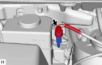
| (b) Disconnect the reservoir level switch connector with the parking brake applied. |
|
(c) Loosen the nut and disconnect the negative (-) auxiliary battery terminal.
(d) Depress the brake pedal 40 times or more to return all the fluid in the accumulator back to the reservoir.
(e) Check that the brake pedal cannot be further depressed.
7. REMOVE REAR WHEEL
Click here
8. DRAIN BRAKE FLUID
NOTICE:
Wash off brake fluid immediately if it comes in contact with any painted surface.
9. DISCONNECT REAR FLEXIBLE HOSE LH
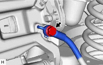
(a) Remove the union bolt and gasket.
(b) Disconnect the rear flexible hose LH from the rear disc brake cylinder assembly LH.
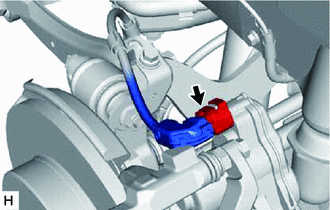
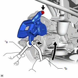
10. REMOVE PARKING BRAKE ACTUATOR ASSEMBLY LH
| (a) Disconnect the connector from the parking brake actuator assembly LH. NOTICE:
|
|
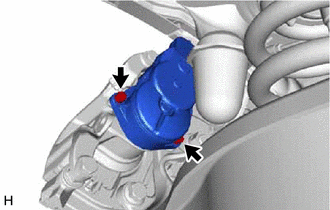
| (b) Using a 5 mm hexagon socket wrench, remove the 2 bolts and parking brake actuator assembly LH. |
|
(c) Remove the O-ring from the rear disc brake cylinder assembly LH.
11. REMOVE REAR DISC BRAKE CYLINDER ASSEMBLY LH
| (a) Hold the rear disc brake cylinder slide pins and remove the 2 bolts and rear disc brake cylinder assembly LH. |
|
12. REMOVE REAR DISC BRAKE PAD KIT
(a) Remove the 2 rear disc brake pads from the rear disc brake cylinder mounting LH.
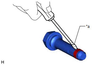
(b) Using a screwdriver, remove the pad wear indicator plates from the rear disc brake pads.
13. REMOVE REAR ANTI-SQUEAL SHIM KIT
(a) Remove the rear No. 1 disc brake anti-squeal shim, rear No. 2 disc brake anti-squeal shim and rear disc brake anti-squeal shim from the rear disc brake pad.
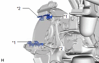
14. REMOVE REAR DISC BRAKE PAD SUPPORT PLATE
| (a) Remove the 2 rear No. 1 disc brake pad support plates and 2 rear No. 2 disc brake pad support plates from the disc brake cylinder mounting. |
|
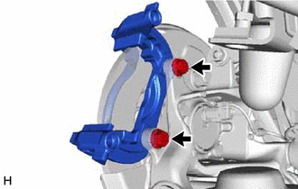
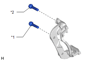
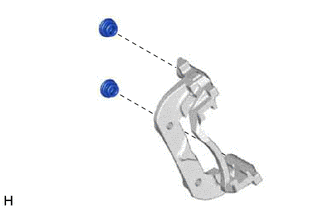
15. REMOVE REAR DISC BRAKE CYLINDER MOUNTING LH
| (a) Remove the 2 bolts and disc brake cylinder mounting from the rear axle. |
|
16. REMOVE REAR DISC BRAKE CYLINDER SLIDE PIN
| (a) Remove the rear disc brake cylinder slide pin from the disc brake cylinder mounting. |
|
17. REMOVE REAR DISC BRAKE REAR CYLINDER SLIDE PIN
(a) Remove the rear disc brake rear cylinder slide pin from the disc brake cylinder mounting.
18. REMOVE REAR DISC BRAKE CYLINDER SLIDE BUSH
| (a) Using a screwdriver with its tip wrapped with protective tape, remove the rear disc brake cylinder slide bush from the rear disc brake rear cylinder slide pin. HINT: Tape the screwdriver tip before use. NOTICE: Do not damage the rear disc brake rear cylinder slide pin. |
|
19. REMOVE REAR DISC BRAKE BUSH DUST BOOT
| (a) Remove the 2 rear disc brake bush dust boots from the disc brake cylinder mounting. |
|
20. REMOVE REAR DISC
| (a) Put matchmarks on the disc and axle hub. |
|
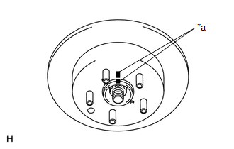
(b) Remove the rear disc.
READ NEXT:
 Disassembly
DISASSEMBLY CAUTION / NOTICE / HINT HINT:
Use the same procedure for the RH and LH sides.
The following procedure is for the LH side.
PROCEDURE 1. REMOVE CYLINDER BOOT (a) Using a screwdriv
Inspection
INSPECTION PROCEDURE 1. CHECK BRAKE CYLINDER AND PISTON (a) Check the cylinder bore and piston for rust or scoring. If necessary, replace the disc brake cylinder and piston. 2. CHECK PAD LINING THICKN
Reassembly
REASSEMBLY CAUTION / NOTICE / HINT HINT:
Use the same procedure for the RH and LH sides.
The following procedure is for the LH side.
PROCEDURE 1. TEMPORARILY INSTALL REAR DISC BRAKE BLEEDER PL
SEE MORE:
Vehicle Speed Signal Circuit between Stereo Component Amplifier and Combination Meter
DESCRIPTION The stereo component amplifier assembly receives a vehicle speed signal from the combination meter assembly to control the ASL function. HINT:
A voltage of 12 V or 5 V is output from each ECU and then input to the combination meter assembly. The signal is changed to a pulse signal at
Installation
INSTALLATION CAUTION / NOTICE / HINT CAUTION: As the engine assembly with transaxle is extremely heavy, the engine lifter may suddenly drop if the instructions listed in the repair manual are not followed. Therefore, always follow the instructions listed in the repair manual when performing this pro
