Lexus NX: Installation
INSTALLATION
PROCEDURE
1. INSTALL BRAKE BOOSTER PUMP ASSEMBLY
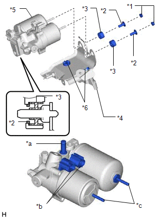
(a) Install the 2 brake actuator bracket cushions to the brake actuator bracket assembly.
| (b) Install the brake booster pump assembly, 2 brake booster pump bushings and 2 brake actuator case collars to the brake actuator bracket assembly with the 2 nuts. Torque: 5.4 N·m {55 kgf·cm, 48 in·lbf} NOTICE:
|
|
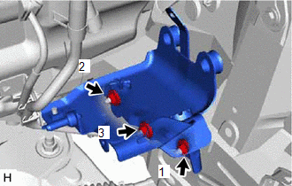
2. INSTALL BRAKE BOOSTER PUMP ASSEMBLY WITH BRACKET
| (a) Install the brake booster pump assembly with bracket with the 3 nuts. Torque: 19 N·m {194 kgf·cm, 14 ft·lbf} NOTICE: Tighten the 3 nuts in the order shown in the illustration. |
|
(b) Attach the brake tube clamp to the brake actuator bracket assembly.
(c) Attach the clamp to the brake booster pump bracket assembly.
(d) Connect the 2 connectors to the brake booster pump assembly.
3. INSTALL NO. 1 BRAKE TUBE CLAMP BRACKET
(a) Install the No. 1 brake tube clamp bracket to the brake booster pump assembly with the bolt.
Torque:
5.0 N·m {51 kgf·cm, 44 in·lbf}
4. INSTALL FRONT NO. 1 BRAKE TUBE
(a) Install the front No. 1 brake tube to the brake booster pump assembly with the bolt.
Torque:
5.0 N·m {51 kgf·cm, 44 in·lbf}
| (b) Using a union nut wrench, connect the front No. 1 brake tube to the brake booster pump assembly to install it. Torque: Specified tightening torque : 15.2 N·m {155 kgf·cm, 11 ft·lbf} HINT:
|
|
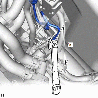
5. CONNECT NO. 1 BRAKE ACTUATOR HOSE
(a) Connect the No. 1 brake actuator hose to the brake booster pump assembly with bracket and secure the hose with the clip.
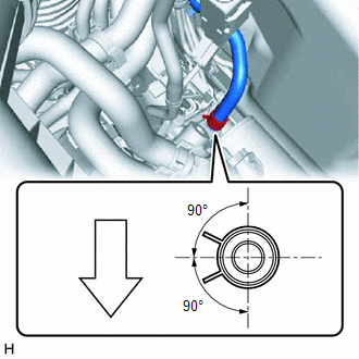
.png) | Front of Vehicle |
NOTICE:
- Connect the No. 1 brake actuator hose with the identification paint mark within 30° of the rib on the brake booster pump assembly with bracket.
- Install the clip within the range shown in the illustration.
6. INSTALL HEATER ACCESSORY ASSEMBLY
| (a) Temporarily install the heater water pump assembly (heater water pump) with the 3 bolts and nut. |
|
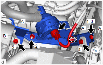
(b) Install the 3 bolts and nut in the order as shown in the illustration.
Torque:
for Bolt A, Nut A :
9.8 N·m {100 kgf·cm, 87 in·lbf}
for Bolt B :
7.7 N·m {79 kgf·cm, 68 in·lbf}
(c) Attach the clamp.
(d) Connect the connector.
7. INSTALL BRAKE BOOSTER WITH MASTER CYLINDER ASSEMBLY
Click here .gif)
8. INSTALL AIR CLEANER CASE SUB-ASSEMBLY
Click here
9. FILL RESERVOIR WITH BRAKE FLUID
10. CONNECT CABLE TO NEGATIVE AUXILIARY BATTERY TERMINAL
Click here
11. INITIALIZATION AFTER RECONECTING AUXILIARY BATTERY TERMINAL
Click here
HINT:
When disconnecting and reconnecting the auxiliary battery, there is an automatic learning function that completes learning when the respective system is used.
Click here
12. INSTALL DECK FLOOR BOX LH
Click here
13. INSTALL REAR DECK FLOOR BOX
Click here
14. INSTALL NO. 3 DECK BOARD SUB-ASSEMBLY
Click here
15. BLEED BRAKE SYSTEM
Click here
READ NEXT:
 Disposal
DISPOSAL PROCEDURE 1. DISPOSE OF BRAKE BOOSTER PUMP ASSEMBLY (a) Remove the accumulator from the brake booster pump assembly. (b) Secure the accumulator in a vise. (c) Using a hacksaw, make a cut i
On-vehicle Inspection
ON-VEHICLE INSPECTION CAUTION / NOTICE / HINT NOTICE: If using a dropper to adjust the fluid amount, make sure that the dropper has not been used with mineral oils, water or deteriorated brake fluid.
SEE MORE:
Initialization
INITIALIZATION INITIALIZE SLIDING ROOF SYSTEM NOTICE:
When the roof glass is adjusted or removed/installed, or the sliding roof drive gear sub-assembly is replaced, the glass position cannot be determined and the sliding roof drive gear sub-assembly must be initialized (pulse sensor initial posit
Diagnosis System
DIAGNOSIS SYSTEM DIAGNOSIS FUNCTION (a) When a malfunction occurs in the dynamic radar cruise control system, the system turns off the cruise control indicator. At the same time, a short buzzer sounds and "Cruise Control Malfunction Visit Your Dealer" is displayed in the multi-information display. T
