Lexus NX: Inspection
INSPECTION
PROCEDURE
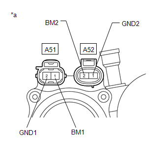
1. INSPECT BRAKE BOOSTER PUMP ASSEMBLY
| (a) Measure the resistance according to the value(s) in the table below. Standard Resistance:
|
|
READ NEXT:
 Installation
INSTALLATION PROCEDURE 1. INSTALL BRAKE BOOSTER PUMP ASSEMBLY (a) Install the 2 brake actuator bracket cushions to the brake actuator bracket assembly. (b) Install the brake booster pump assembly,
Disposal
DISPOSAL PROCEDURE 1. DISPOSE OF BRAKE BOOSTER PUMP ASSEMBLY (a) Remove the accumulator from the brake booster pump assembly. (b) Secure the accumulator in a vise. (c) Using a hacksaw, make a cut i
SEE MORE:
Front Right Center Sensor (C1AE3)
DESCRIPTION The front center ultrasonic sensor (FRC sensor) is installed to the front bumper. The clearance warning ECU assembly detects obstacles based on signals received from the front center ultrasonic sensor (FRC sensor). If the front center ultrasonic sensor (FRC sensor) has an open circuit or
Navigation Ecu
ComponentsCOMPONENTS ILLUSTRATION *1 NAVIGATION ECU *2 NO. 1 RADIO BRACKET *3 NO. 2 RADIO BRACKET *4 RADIO RECEIVER ASSEMBLY WITH BRACKET *5 NAVIGATION WIRE - - RemovalREMOVAL PROCEDURE 1. REMOVE RADIO RECEIVER ASSEMBLY WITH BRACKET Click here 2. REMOVE NO. 1 RA
© 2016-2026 Copyright www.lexunx.com
