Lexus NX: Removal
REMOVAL
PROCEDURE
1. REMOVE INSTRUMENT PANEL FINISH PLATE
2. REMOVE MULTI-DISPLAY ASSEMBLY WITH BRACKET
Click here .gif)
3. REMOVE CONSOLE ARMREST ASSEMBLY
Click here
4. REMOVE UPPER REAR CONSOLE PANEL
Click here
5. REMOVE UPPER NO. 1 CONSOLE PANEL GARNISH
Click here
6. REMOVE UPPER NO. 2 CONSOLE PANEL GARNISH
Click here
7. REMOVE INSTRUMENT SIDE PANEL RH
Click here
8. REMOVE INSTRUMENT SIDE PANEL LH
Click here
9. REMOVE NO. 1 INSTRUMENT PANEL SAFETY PAD SUB-ASSEMBLY
Click here
10. REMOVE NO. 1 INSTRUMENT PANEL UNDER COVER SUB-ASSEMBLY
Click here
11. REMOVE LOWER NO. 1 INSTRUMENT PANEL FINISH PANEL
Click here
12. REMOVE NO. 1 SWITCH HOLE BASE
Click here
13. REMOVE NO. 2 INSTRUMENT PANEL SAFETY PAD SUB-ASSEMBLY
Click here
14. REMOVE CENTER INSTRUMENT CLUSTER FINISH PANEL ASSEMBLY
Click here
15. REMOVE SHIFT LEVER KNOB SUB-ASSEMBLY
Click here
16. REMOVE UPPER REAR CONSOLE PANEL SUB-ASSEMBLY
Click here
17. REMOVE SHIFT POSITION INDICATOR
Click here
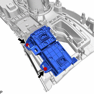
18. REMOVE INTEGRATION CONTROL AND PANEL ASSEMBLY
| (a) Remove the 2 screws and integration control and panel assembly to the rear upper console panel sub-assembly. |
|
READ NEXT:
 Inspection
INSPECTION PROCEDURE 1. INSPECT INTEGRATION CONTROL AND PANEL ASSEMBLY (a) Measure the resistance according to the value(s) in the table below. Standard Resistance: Tester Connection Switch C
Installation
INSTALLATION PROCEDURE 1. INSTALL INTEGRATION CONTROL AND PANEL ASSEMBLY (a) Install the integration control and panel assembly to the rear upper console panel sub-assembly with the 2 screws. HINT:
SEE MORE:
Removal
REMOVAL PROCEDURE 1. REMOVE DOOR SCUFF PLATE ASSEMBLY LH Click here 2. REMOVE COWL SIDE TRIM BOARD LH Click here 3. REMOVE NO. 1 INSTRUMENT PANEL UNDER COVER SUB-ASSEMBLY Click here 4. REMOVE GLOVE COMPARTMENT DOOR ASSEMBLY Click here 5. REMOVE ACCELERATION SENSOR (a) for RH side: (1) Dis
Disassembly
DISASSEMBLY PROCEDURE 1. REMOVE AIR FILTER CASE (a) Detach the claw and guide and remove the air filter case. 2. REMOVE AIR REFINER ELEMENT (a) Remove the air refiner element. 3. REMOVE BLOWER WITH FAN MOTOR SUB-ASSEMBLY (a) Remove the 3 screws and the blower with fa
