Lexus NX: Relay
On-vehicle Inspection
ON-VEHICLE INSPECTION
PROCEDURE
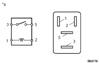
1. INSPECT PTC HEATER RELAY(PTC HTR NO. 1, NO. 3)
| (a) Measure the resistance according to the value(s) in the table below. Standard Resistance:
|
|
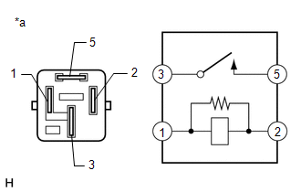
2. INSPECT PTC HEATER RELAY(PTC HTR NO. 2)
| (a) Measure the resistance according to the value(s) in the table below. Standard Resistance:
|
|
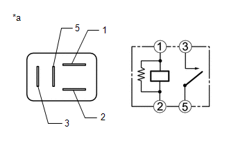
3. INSPECT WATER PUMP RELAY
| (a) Measure the resistance according to the value(s) in the table below. Standard Resistance:
If the result is not as specified, replace the water pump relay. |
|
READ NEXT:
 Components
COMPONENTS ILLUSTRATION *1 CONSOLE ARMREST ASSEMBLY *2 COOLER THERMISTOR (ROOM TEMPERATURE SENSOR) *3 COWL SIDE TRIM BOARD LH *4 DOOR SCUFF PLATE ASSEMBLY LH *5 INSTRUMENT SI
Removal
REMOVAL PROCEDURE 1. REMOVE DOOR SCUFF PLATE ASSEMBLY LH Click here 2. REMOVE COWL SIDE TRIM BOARD LH Click here 3. REMOVE CONSOLE ARMREST ASSEMBLY Click here 4. REMOVE UPPER REAR CONSOL
SEE MORE:
Adjustment (one Time Recognition)
ADJUSTMENT (ONE TIME RECOGNITION) CAUTION / NOTICE / HINT NOTICE: Make sure to read Before Starting Adjustment before proceeding with work. Click here PROCEDURE 1. SECURE APPROPRIATE AREA FOR PERFORMING LEARNING (a) Park the vehicle on a level surface. HINT:
Make sure that the target recogni
Lost Communication with ECM / PCM "A" (U0100-530,U0126-735,U0129-527,U0129-528,U0140-146,U0151-763,U0164-827,U1107-436)
DESCRIPTION The hybrid vehicle control ECU transmits and receives signals via CAN communication to and from the ECM, skid control ECU assembly, power steering ECU assembly, main body ECU, airbag ECU assembly, and air conditioning amplifier assembly. DTC No. Detection Item DTC Detection Condit
