Lexus NX: Components
Lexus NX Service Manual / Brake / Brake Control / Dynamic Control Systems / Brake Hold Switch / Components
COMPONENTS
ILLUSTRATION
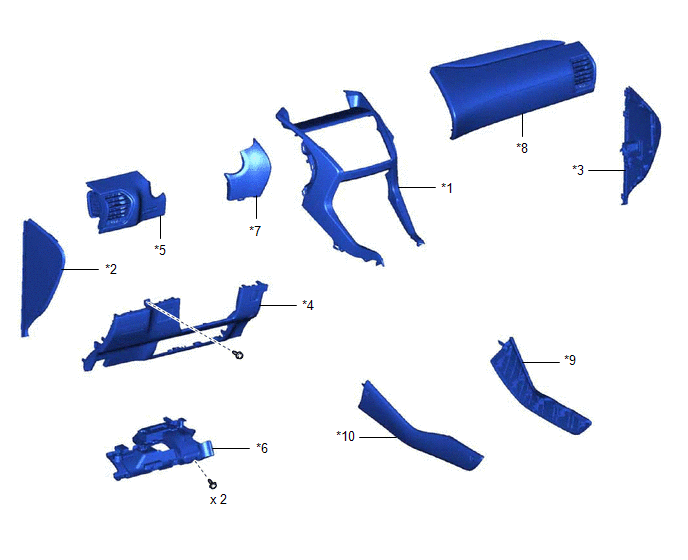
| *1 | CENTER INSTRUMENT CLUSTER FINISH PANEL ASSEMBLY | *2 | INSTRUMENT SIDE PANEL LH |
| *3 | INSTRUMENT SIDE PANEL RH | *4 | LOWER NO. 1 INSTRUMENT PANEL FINISH PANEL |
| *5 | NO. 1 INSTRUMENT PANEL SAFETY PAD SUB-ASSEMBLY | *6 | NO. 1 INSTRUMENT PANEL UNDER COVER SUB-ASSEMBLY |
| *7 | NO. 1 SWITCH HOLE BASE | *8 | NO. 2 INSTRUMENT PANEL SAFETY PAD SUB-ASSEMBLY |
| *9 | UPPER NO. 1 CONSOLE PANEL GARNISH | *10 | UPPER NO. 2 CONSOLE PANEL GARNISH |
ILLUSTRATION
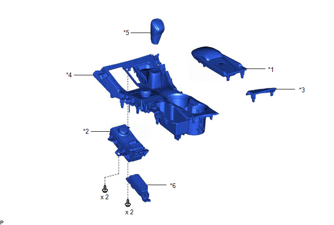
| *1 | CONSOLE ARMREST ASSEMBLY | *2 | INTEGRATION CONTROL AND PANEL ASSEMBLY (BRAKE HOLD SWITCH) |
| *3 | REAR UPPER CONSOLE PANEL | *4 | REAR UPPER CONSOLE PANEL SUB-ASSEMBLY |
| *5 | SHIFT LEVER KNOB SUB-ASSEMBLY | *6 | SHIFT POSITION INDICATOR |
READ NEXT:
 Removal
REMOVAL PROCEDURE 1. REMOVE CONSOLE ARMREST ASSEMBLY Click here 2. REMOVE REAR UPPER CONSOLE PANEL Click here 3. REMOVE UPPER NO. 2 CONSOLE PANEL GARNISH Click here 4. REMOVE UPPER NO. 1 C
Inspection
INSPECTION PROCEDURE 1. INSPECT INTEGRATION CONTROL AND PANEL ASSEMBLY (BRAKE HOLD SWITCH) (a) Measure the resistance according to the value(s) in the table below. Standard Resistance: Tester C
Installation
INSTALLATION PROCEDURE 1. INSTALL INTEGRATION CONTROL AND PANEL ASSEMBLY (BRAKE HOLD SWITCH) (a) Install the integration control and panel assembly (brake hold switch) to the upper rear console pan
SEE MORE:
Drive Motor "A" Inverter Performance (P0A78-121)
DTC SUMMARY MALFUNCTION DESCRIPTION This DTC indicates that an overvoltage in the inverter has occurred. The cause of this malfunction may be one of the following: Area Main Malfunction Description Step Inverter low-voltage circuit The connectors are not connected properly 3 Resol
Inspection
INSPECTION PROCEDURE 1. INSPECT NAVIGATION ANTENNA ASSEMBLY (a) Measure the resistance according to the value(s) in the table below. Standard Resistance: Tester Antenna Tester Connection Condition Specified Condition Navigation antenna 1 - 2 Always 50 to 500 Ω LTE sub-ann
© 2016-2026 Copyright www.lexunx.com
