Lexus NX: Seat Heater Control (for Front Seat)
Components
COMPONENTS
ILLUSTRATION
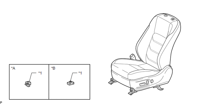
| *A | for L-Sport | *B | for F-Sport |
| *1 | SEAT HEATER CONTROL SUB-ASSEMBLY LH | - | - |
Removal
REMOVAL
CAUTION / NOTICE / HINT
CAUTION:
Wear protective gloves. Sharp areas on the parts may injure your hands.
HINT:
- Use the same procedure for the RH and LH sides.
- The procedure listed below is for the LH side.
PROCEDURE
1. REMOVE FRONT SEAT ASSEMBLY LH
Click here .gif)
2. REMOVE SEAT HEATER CONTROL SUB-ASSEMBLY LH (w/ Seat Heater System)
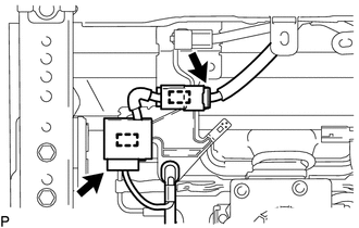
| (a) for L-Sport: (1) Disconnect the 2 connectors. (2) Detach the 2 clamps to remove the seat heater control sub-assembly LH. |
|
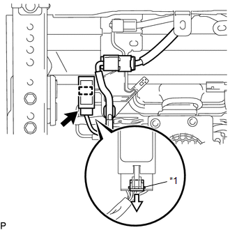
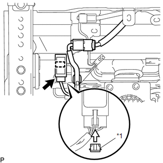
| (b) for F-Sport: (1) Remove the connector lock. (2) Disconnect the seat heater control connector. (3) Detach the clamp to remove the seat heater control sub-assembly LH. |
|
Installation
INSTALLATION
CAUTION / NOTICE / HINT
CAUTION:
Wear protective gloves. Sharp areas on the parts may injure your hands.
HINT:
- Use the same procedure for the RH and LH sides.
- The procedure listed below is for the LH side.
PROCEDURE
1. INSTALL SEAT HEATER CONTROL SUB-ASSEMBLY LH (w/ Seat Heater System)
(a) for L-Sport:
(1) Attach the 2 clamps to install the seat heater control sub-assembly LH.
(2) Connect the 2 connectors.
| (b) for F-Sport: (1) Attach the clamp to install the seat heater control sub-assembly LH. (2) Connect the seat heater control connector. (3) Install the connector lock. |
|
2. INSTALL FRONT SEAT ASSEMBLY LH
Click here .gif)
READ NEXT:
 Components
COMPONENTS ILLUSTRATION *A for RH Side *B for Manual Seat *C for Power Seat - - *1 REAR SEATBACK ASSEMBLY RH *2 REAR SEATBACK BOARD CARPET ASSEMBLY RH *3 REAR SEATB
Removal
REMOVAL CAUTION / NOTICE / HINT CAUTION: Wear protective gloves. Sharp areas on the parts may injure your hands. PROCEDURE 1. REMOVE REAR SEATBACK ASSEMBLY LH (a) for Manual Seat: Click here (b) for
SEE MORE:
On-vehicle Inspection
ON-VEHICLE INSPECTION CAUTION / NOTICE / HINT NOTICE:
When the brake pedal is first depressed after replacing the brake pads or pushing back the disc brake piston, DTC C1214 may be output. As there is no malfunction, clear the DTC.
While the auxiliary battery is connected, even if the power swi
Disassembly
DISASSEMBLY PROCEDURE 1. REMOVE ENGINE COVER JOINT (a) Remove the 3 engine cover joints. 2. REMOVE SPARK PLUG Click here 3. REMOVE KNOCK CONTROL SENSOR Click here 4. REMOVE ENGINE COOLANT TEMPERATURE SENSOR Click here 5. REMOVE ENGINE OIL PRESSURE SWITCH ASSEMBLY Click here 6.
