Lexus NX: Removal
REMOVAL
CAUTION / NOTICE / HINT
CAUTION:
Wear protective gloves. Sharp areas on the parts may injure your hands.
PROCEDURE
1. REMOVE REAR SEATBACK ASSEMBLY LH
(a) for Manual Seat:
Click here .gif)
(b) for Power Seat:
Click here
2. REMOVE REAR SEATBACK ASSEMBLY RH
(a) for Manual Seat:
Click here
(b) for Power Seat:
Click here
3. REMOVE REAR SEATBACK COVER
Click here
4. REMOVE REAR SEATBACK BOARD CARPET ASSEMBLY RH (for RH Side)
Click here
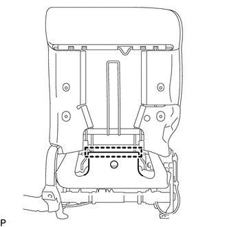
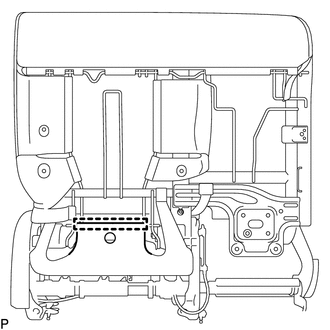
5. REMOVE SEAT HEATER CONTROL SUB-ASSEMBLY (for RH Side)
(a) for Manual Seat:
| (1) Detach the hook. |
|
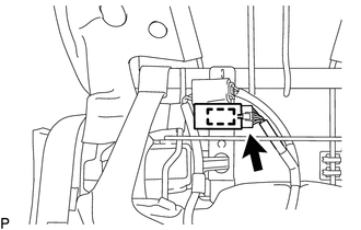
| (2) Disconnect the connector. |
|
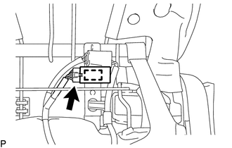
(3) Detach the clamp and remove the seat heater control sub-assembly.
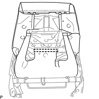
(b) for Power Seat:
| (1) Detach the hook. |
|
| (2) Disconnect the connector. |
|
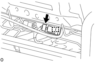
(3) Detach the clamp and remove the seat heater control sub-assembly.
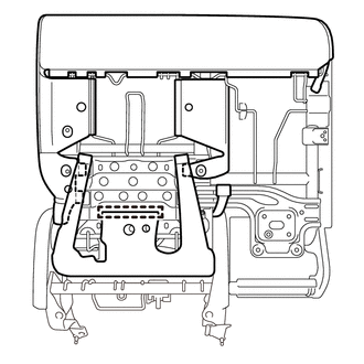
6. REMOVE REAR SEATBACK BOARD CARPET ASSEMBLY LH (for LH Side)
Click here
7. REMOVE SEAT HEATER CONTROL SUB-ASSEMBLY (for LH Side)
(a) for Manual Seat:
| (1) Detach the hook. |
|
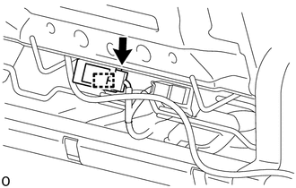
| (2) Disconnect the connector. |
|
(3) Detach the clamp and remove the seat heater control sub-assembly.
(b) for Power Seat:
| (1) Detach the hook. |
|
| (2) Disconnect the connector. |
|
(3) Detach the clamp and remove the seat heater control sub-assembly.
READ NEXT:
 Installation
INSTALLATION CAUTION / NOTICE / HINT CAUTION: Wear protective gloves. Sharp areas on the parts may injure your hands. PROCEDURE 1. INSTALL SEAT HEATER CONTROL SUB-ASSEMBLY (for LH Side) (a) for Manual
Seat Heater Switch(for Rear Seat)
ComponentsCOMPONENTS ILLUSTRATION *1 CONSOLE BOX REGISTER ASSEMBLY *2 REAR CONSOLE END PANEL SUB-ASSEMBLY *3 REFRESHING SEAT SWITCH *4 DUCT RemovalREMOVAL PROCEDURE 1. REMOVE
SEE MORE:
How To Proceed With Troubleshooting
CAUTION / NOTICE / HINT HINT: Use the following procedures to troubleshoot the rear power seat control system. PROCEDURE 1. VEHICLE BROUGHT TO WORKSHOP
NEXT 2. CUSTOMER PROBLEM ANALYSIS HINT:
In troubleshooting, confirm that the problem symptoms have been accura
Reassembly
REASSEMBLY CAUTION / NOTICE / HINT NOTICE:
Handle components indoors as much as possible to prevent foreign matter from entering and adhering to headlight assembly components.
Do not reuse parts which have reduced fastening ability due to thread damage.
When installing components, make sure t
