Lexus NX: Sensor (Motor) Failure (B2341,B2344)
DESCRIPTION
When the sliding roof drive gear sub-assembly (sliding roof ECU) detects a motor malfunction and the sliding roof operation is stopped, DTC B2341 is stored.
When the sliding roof drive gear sub-assembly (sliding roof ECU) detects a gear position malfunction and the sliding roof operation is stopped, DTC B2344 is stored.
| DTC No. | Detection Item | DTC Detection Condition | Trouble Area |
|---|---|---|---|
| B2341 | Sensor (Motor) Failure | Sensor (motor) failure (When the sliding roof drive gear sub-assembly (sliding roof ECU) enters fail-safe mode due to a problem with the motor) |
|
| B2344 | Position Failure | Position failure (When the sliding roof drive gear sub-assembly (sliding roof ECU) enters fail-safe mode due to a problem with the gear position) |
|
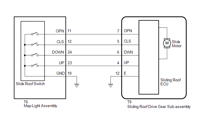
WIRING DIAGRAM
CAUTION / NOTICE / HINT
NOTICE:
-
If the sliding roof drive gear sub-assembly (sliding roof ECU) is replaced, the sliding roof drive gear sub-assembly (sliding roof ECU) must be initialized.
Click here
.gif)
-
The sliding roof system uses the LIN communication system. First, confirm that there are no malfunctions in the LIN communication system. Refer to How to Proceed with Troubleshooting.
Click here
PROCEDURE
| 1. | CHECK SLIDING ROOF OPERATION |
(a) Check the sliding roof auto operation.
Click here
OK:
Auto operation operates normally.
| NG | .gif) | GO TO STEP 3 |
|
.gif)
| 2. | CHECK DTC OUTPUT |
(a) Clear the DTCs.
Click here
(b) Check for DTCs.
Click here
OK:
DTCs B2341 and B2344 are not output.
| OK | | USE SIMULATION METHOD TO CHECK |
| NG | | REPLACE SLIDING ROOF DRIVE GEAR SUB-ASSEMBLY |
| 3. | INITIALIZE SLIDING ROOF DRIVE GEAR SUB-ASSEMBLY |
(a) Check that the sliding roof drive gear sub-assembly (sliding roof ECU) can be initialized.
Click here
OK:
Sliding roof drive gear sub-assembly (sliding roof ECU) can be initialized.
| NG | | GO TO STEP 5 |
|
| 4. | CHECK DTC OUTPUT |
(a) Clear the DTCs.
Click here
(b) Check for DTCs.
Click here
OK:
DTCs B2341 and B2344 are not output.
| OK | | END (MALFUNCTION DUE TO INITIALIZATION FAILURE) |
| NG | | REPLACE SLIDING ROOF DRIVE GEAR SUB-ASSEMBLY |
| 5. | PERFORM ACTIVE TEST USING TECHSTREAM (Slide Roof) |
(a) Connect the Techstream to the DLC3.
(b) Turn the power switch on (IG).
(c) Turn the Techstream on.
(d) Enter the following menus: Body Electrical / Sliding Roof / Active Test.
(e) Perform the Active Test according to the display on the Techstream.
Body Electrical > Sliding Roof > Active Test| Tester Display | Measurement Item | Control Range | Diagnostic Note |
|---|---|---|---|
| Slide Roof | Operate sliding roof motor | OFF / Opn/Dwn / Clos/Up | - |
| Tester Display |
|---|
| Slide Roof |
OK:
Slide roof is operated using Techstream.
| NG | | REPLACE SLIDING ROOF DRIVE GEAR SUB-ASSEMBLY |
|
| 6. | READ VALUE USING TECHSTREAM (Open Switch, Close Switch, Up Switch, Down Switch) |
(a) Connect the Techstream to the DLC3.
(b) Turn the power switch on (IG).
(c) Turn the Techstream on.
(d) Enter the following menus: Body Electrical / Sliding Roof / Data List.
(e) Read the Data List according to the display on the Techstream.
Body Electrical > Sliding Roof > Data List| Tester Display | Measurement Item | Range | Normal Condition | Diagnostic Note |
|---|---|---|---|---|
| Open Switch | OPEN switch signal | OFF or ON | OFF: OPEN switch not pressed ON: OPEN switch pressed | - |
| Close Switch | CLOSE switch signal | OFF or ON | OFF: CLOSE switch not pressed ON: CLOSE switch pressed | - |
| Up Switch | UP switch signal | OFF or ON | OFF: UP switch not pressed ON: UP switch pressed | - |
| Down Switch | DOWN switch signal | OFF or ON | OFF: DOWN switch not pressed ON: DOWN switch pressed | - |
| Tester Display |
|---|
| Open Switch |
| Close Switch |
| Up Switch |
| Down Switch |
OK:
The Techstream display changes according to switch operation as shown in the table.
| OK | | REPLACE SLIDING ROOF DRIVE GEAR SUB-ASSEMBLY |
|
| 7. | INSPECT MAP LIGHT ASSEMBLY |
(a) Remove the map light assembly (slide roof switch).
Click here
(b) Inspect the map light assembly (slide roof switch).
Click here
| NG | | REPLACE MAP LIGHT ASSEMBLY |
|
| 8. | CHECK HARNESS AND CONNECTOR (SLIDING ROOF DRIVE GEAR SUB-ASSEMBLY - MAP LIGHT ASSEMBLY AND BODY GROUND) |
(a) Disconnect the T9 sliding roof drive gear sub-assembly connector.
(b) Disconnect the T6 map light assembly connector.
(c) Measure the resistance according to the value(s) in the table below.
Standard Resistance:
| Tester Connection | Condition | Specified Condition |
|---|---|---|
| T9-4 (UP) - T6-23 (UP) | Always | Below 1 Ω |
| T9-4 (UP) or T6-23 (UP) - Body ground | Always | 10 kΩ or higher |
| T9-5 (CLS) - T6-12 (CLS) | Always | Below 1 Ω |
| T9-5 (CLS) or T6-12 (CLS) - Body ground | Always | 10 kΩ or higher |
| T9-6 (DWN) - T6-24 (DOWN) | Always | Below 1 Ω |
| T9-6 (DWN) or T6-24 (DOWN) - Body ground | Always | 10 kΩ or higher |
| T9-7 (OPN) - T6-11 (OPN) | Always | Below 1 Ω |
| T9-7 (OPN) or T6-11 (OPN) - Body ground | Always | 10 kΩ or higher |
| T9-12 (E) - Body ground | Always | Below 1 Ω |
| T6-19 (GND) - Body ground | Always | Below 1 Ω |
| OK | | REPLACE SLIDING ROOF DRIVE GEAR SUB-ASSEMBLY |
| NG | | REPAIR OR REPLACE HARNESS OR CONNECTOR |
READ NEXT:
 Switch Failure (B2342)
DESCRIPTION This DTC is stored when the sliding roof drive gear sub-assembly (sliding roof ECU) detects that the map light assembly (slide roof switch) is stuck for 30 seconds or more. DTC No. De
Position Initialization Incomplete (B2343)
DESCRIPTION This DTC is stored when the sliding roof drive gear sub-assembly (sliding roof ECU) has not been initialized. DTC No. Detection Item DTC Detection Condition Trouble Area B2343
Remote Control System does not Operate
DESCRIPTION The main body ECU (multiplex network body ECU) receives remote control signals from the driver door key cylinder or wireless transmitter. Then, the main body ECU (multiplex network body EC
SEE MORE:
Portable Player cannot be Registered
CAUTION / NOTICE / HINT HINT: Some versions of "Bluetooth" compatible audio players may not function properly, or the functions may be limited using the radio receiver assembly, even if the portable audio player itself can play files. Click here PROCEDURE 1. CHECK THAT PORTABLE PLAYER IS "B
Installation
INSTALLATION CAUTION / NOTICE / HINT HINT:
Use the same procedure for the RH and LH sides.
The procedure listed below is for the LH side.
PROCEDURE 1. INSTALL OUTER MIRROR LH (a) w/o EC Mirror: (1) Connect the connector. (b) w/ EC Mirror: (1) Connect the connector(a). (2) C
