Lexus NX: Installation
INSTALLATION
CAUTION / NOTICE / HINT
HINT:
- Use the same procedure for the RH and LH sides.
- The procedure listed below is for the LH side.
-
A bolt without a torque specification is shown in the standard bolt chart.
Click here
.gif)
PROCEDURE
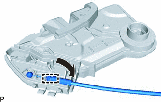
1. INSTALL FRONT DOOR INSIDE LOCKING CABLE ASSEMBLY LH
| (a) Attach the clamp to install the front door inside locking cable assembly LH to the front door lock assembly LH. |
|
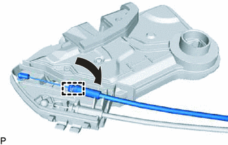
2. INSTALL FRONT DOOR LOCK REMOTE CONTROL CABLE ASSEMBLY LH
| (a) Attach the clamp to install the front door lock remote control cable assembly LH to the front door lock assembly LH. |
|
3. INSTALL FRONT DOOR LOCK COVER SUB-ASSEMBLY LH
(a) Attach the 2 guides.
(b) Attach the 2 claws to install the front door lock cover sub-assembly LH.
4. INSTALL DOOR LOCK WIRING HARNESS SEAL
(a) Install a new door lock wiring harness seal to the front door lock assembly LH.
5. INSTALL FRONT DOOR LOCK ASSEMBLY LH
NOTICE:
- When reusing the removed front door lock assembly, replace the door lock wiring harness seal on the connector with a new one.
- Do not allow grease or dust to adhere to the door lock wiring harness seal surface of the connector.
- Reusing the door lock wiring harness seal or using a damaged door lock wiring harness seal may cause water intrusion. This may result in a malfunction of the front door lock assembly.
(a) Apply MP grease to the sliding parts of the front door lock assembly LH.
(b) Insert the front door lock open rod LH into the front door lock assembly LH.
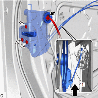
| *1 | Front Door Lock Open Rod LH |
.png) | Upward |
(c) Make sure that the front door lock open rod is securely connected to the front door lock assembly LH.
(d) Using a T30 "TORX" socket wrench, install the front door lock assembly LH with the 3 screws.
Torque:
5.0 N·m {51 kgf·cm, 44 in·lbf}
(e) Connect the connector.
6. INSTALL FRONT DOOR LOCK CYLINDER ASSEMBLY LH (for Driver Side)
Click here
7. INSTALL FRONT DOOR OUTSIDE HANDLE ASSEMBLY LH
Click here
8. INSTALL FRONT DOOR REAR LOWER FRAME SUB-ASSEMBLY LH
Click here
9. INSTALL FRONT DOOR GLASS SUB-ASSEMBLY LH
Click here
10. INSTALL FRONT DOOR GLASS RUN LH
Click here
11. INSTALL FRONT DOOR SERVICE HOLE COVER LH
Click here
12. INSTALL FRONT DOOR ARMREST SET BRACKET LH
Click here
13. INSTALL FRONT DOOR INNER GLASS WEATHERSTRIP LH
Click here
14. INSTALL FRONT DOOR TRIM BOARD SUB-ASSEMBLY LH
Click here
15. INSTALL POWER WINDOW REGULATOR SWITCH ASSEMBLY WITH FRONT DOOR ARMREST BASE PANEL (for Front Passenger Side)
Click here
16. INSTALL POWER WINDOW REGULATOR MASTER SWITCH ASSEMBLY WITH FRONT DOOR ARMREST BASE PANEL (for Driver Side)
Click here
17. INSTALL FRONT DOOR INSIDE HANDLE BEZEL PLUG LH
Click here
18. INSTALL FRONT DOOR TRIM COVER LH
Click here
19. CONNECT CABLE TO NEGATIVE AUXILIARY BATTERY TERMINAL
20. INITIALIZATION AFTER RECONNECTING AUXILIARY BATTERY TERMINAL
Click here
HINT:
When disconnecting and reconnecting the auxiliary battery, there is an automatic learning function that completes learning when the respective system is used.
Click here
21. INSTALL DECK FLOOR BOX LH
Click here
22. INSTALL REAR DECK FLOOR BOX
Click here
23. INSTALL NO. 3 DECK BOARD SUB-ASSEMBLY
Click here
24. CHECK SRS WARNING LIGHT
Click here
25. INITIALIZE POWER WINDOW CONTROL SYSTEM
Click here
26. CHECK POWER WINDOW CONTROL SYSTEM
Click here
27. CHECK POWER DOOR LOCK CONTROL SYSTEM
Click here
READ NEXT:
 Precaution
PRECAUTION PRECAUTIONS WHEN USING TECHSTREAM (a) When using the Techstream with the vehicle power switch off, connect the Techstream to the DLC3 and turn a courtesy light switch on and off at interval
Parts Location
PARTS LOCATION ILLUSTRATION *1 ENGINE ROOM RELAY BLOCK
- AM2 FUSE
- - ILLUSTRATION *A w/o Power Back Door System *B w/ Power Back Door System *1 BACK DOOR LOCK ASSEM
SEE MORE:
System Description
SYSTEM DESCRIPTION WASHER-LINKED FUNCTION (a) This system operates the front wipers at low speed immediately after spraying a jet of washer fluid when the front washer switch is turned on for 0.3 seconds or more. The system operates the front wipers at low speed for approximately 2.2 seconds and the
Calibration
CALIBRATION NOTICE: When any of the following parts have been replaced, perform adjustment shown in the following table. If not, the intuitive parking assist system may not operate correctly. ADJUST INTUITIVE PARKING ASSIST SYSTEM (a) The necessary procedures (adjustment, calibration, initialization
