Lexus NX: Short to GND in Immobiliser System Power Source Circuit (B278A)
DESCRIPTION
When there is a short to GND in the power supply for the transponder key amplifier of the power switch, the certification ECU (smart key ECU assembly) stores this DTC.
| DTC No. | Detection Item | DTC Detection Condition | Trouble Area | Note |
|---|---|---|---|---|
| B278A | Short to GND in Immobiliser System Power Source Circuit | A short to GND in the power supply of the transponder key amplifier of the power switch (VC5 - VC5) detected. (1 trip detection logic*) |
| DTC output confirmation operation:
|
- *: Only output while a malfunction is present.
| Vehicle Condition when Malfunction Detected | Fail-safe Operation when Malfunction Detected |
|---|---|
| Hybrid control system cannot be started when transmitter battery is depleted by holding transmitter near power switch and pressing and holding power switch with shift lever in P | - |
| DTC No. | Data List and Active Test |
|---|---|
| B278A | - |
WIRING DIAGRAM
.png)
CAUTION / NOTICE / HINT
NOTICE:
- When using the Techstream with the power switch off, connect the Techstream to the DLC3 and turn a courtesy light switch on and off at intervals of 1.5 seconds or less until communication between the Techstream and the vehicle begins. Then select the vehicle type under manual mode and enter the following menus: Body Electrical / Smart Access. While using the Techstream, periodically turn a courtesy light switch on and off at intervals of 1.5 seconds or less to maintain communication between the Techstream and the vehicle.
-
Before replacing the certification ECU (smart key ECU assembly), refer to Registration.
Click here
.gif)
- After repair, confirm that no DTCs are output by performing "DTC Output Confirmation Operation."
PROCEDURE
| 1. | CHECK CERTIFICATION ECU (SMART KEY ECU ASSEMBLY) |
(a) Using an oscilloscope, check the waveform.
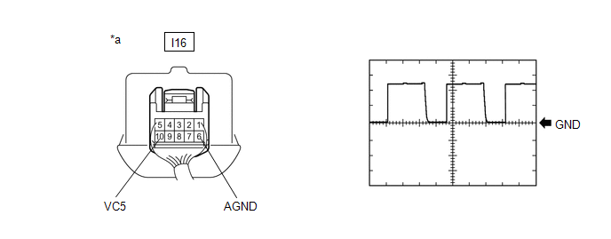
| *a | Component with harness connected (Power Switch) | - | - |
Measurement Condition:
| Tester Connection | Condition | Tool Setting | Specified Condition |
|---|---|---|---|
| I16-10 (VC5) - I16-6 (AGND) | Power switch off, key not in cabin, within 30 seconds after power switch pressed | 2 V/DIV., 200 ms./DIV. | Pulse generation |
OK:
The waveform is similar to that shown in the illustration.
| OK | .gif) | REPLACE POWER SWITCH |
|
.gif)
| 2. | CHECK HARNESS AND CONNECTOR (CERTIFICATION ECU (SMART KEY ECU ASSEMBLY) - POWER SWITCH) |
(a) Disconnect the I53 certification ECU (smart key ECU assembly) connector.
(b) Disconnect the I16 power switch connector.
(c) Measure the resistance according to the value(s) in the table below.
Standard Resistance:
| Tester Connection | Condition | Specified Condition |
|---|---|---|
| I53-15 (VC5) - I16-10 (VC5) | Always | Below 1 Ω |
| I53-12 (AGND) - I16-6 (AGND) | Always | Below 1 Ω |
| I53-15 (VC5) or I16-10 (VC5) - Body ground | Always | 10 kΩ or higher |
| I53-12 (AGND) or I16-6 (AGND) - Body ground | Always | 10 kΩ or higher |
| NG | | REPAIR OR REPLACE HARNESS OR CONNECTOR |
|
| 3. | CHECK CERTIFICATION ECU (SMART KEY ECU ASSEMBLY) |
(a) Reconnect the I53 certification ECU (smart key ECU assembly) connector.
(b) Reconnect the I16 power switch connector.
(c) Measure the voltage according to the value(s) in the table below.
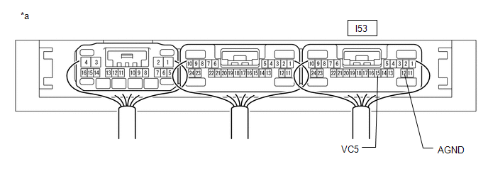
| *a | Component with harness connected (Certification ECU (Smart Key ECU Assembly)) | - | - |
Standard Voltage:
| Tester Connection | Condition | Specified Condition |
|---|---|---|
| I53-15 (VC5) - I53-12 (AGND) | Power switch off, brake pedal not depressed, 30 seconds or more elapsed after driver door opened and then closed | Below 1 V |
| OK | | REPLACE POWER SWITCH |
| NG | | REPLACE CERTIFICATION ECU (SMART KEY ECU ASSEMBLY) |
READ NEXT:
 ID BOX EEPROM Malfunction (B2790)
DESCRIPTION When an internal malfunction occurs in the ID code box (immobiliser code ECU), the certification ECU (smart key ECU assembly) stores this DTC. DTC No. Detection Item DTC Detection C
Engine Immobiliser System Malfunction (B2799-790)
DESCRIPTION When there is a communication malfunction between the hybrid vehicle control ECU and ID code box (immobiliser code ECU), or when the communication ID codes do not match, the hybrid vehicle
Engine Immobiliser System Communication Line High Fixation (B279A-186)
DESCRIPTION When the communication line (IMI - EFIO) between the hybrid vehicle control ECU and ID code box (immobiliser code ECU) is stuck high, the hybrid vehicle control ECU stores this DTC. DTC
SEE MORE:
Disassembly
DISASSEMBLY CAUTION / NOTICE / HINT HINT:
Use the same procedure for the RH and LH sides.
The procedure listed below is for the LH side.
PROCEDURE 1. REMOVE NO. 3 MOULDING TAPE (a) Remove the No. 3 moulding tape. HINT: Do not pull on the No. 3 moulding tape. Instead, roll the tape up with y
Diagnostic Trouble Code Chart
DIAGNOSTIC TROUBLE CODE CHART Electronically Controlled Brake System DTC No. Detection Item INF Code Note Link C1202 Master Reservoir Level Malfunction 371 - - C1203 ECM Communication Circuit - - C1210 Zero Point Calibration of Yaw Rate Sensor undone
