Lexus NX: Inverter Low-voltage Circuit
DESCRIPTION
The cause of the malfunction may be the low-voltage circuit.
Check whether there is an open circuit in the inverter +B low-voltage power source system or a problem in the communication between the hybrid vehicle control ECU and inverter.
Related Parts Check| Area | Inspection | Step |
|---|---|---|
| Inverter +B low-voltage power source system check | Check for inverter overcurrent malfunction. | 1, 2 |
| Communication malfunction between hybrid vehicle control ECU and MG-ECU inside inverter with converter assembly | Check for inverter overcurrent malfunction due to communication malfunction. | 3, 4 |
| Check for short to ground in inverter +B low-voltage power source system | - | 5, 6, 7 |
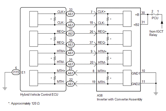
WIRING DIAGRAM
CAUTION / NOTICE / HINT
This step is referenced from the procedures for each DTC.
If the inspection results below are normal, perform the next procedure for the referenced DTC.
CAUTION:
- Before inspecting the high-voltage system or disconnecting the low voltage connector of the inverter with converter assembly, take safety precautions such as wearing insulated gloves and removing the service plug grip to prevent electrical shocks. After removing the service plug grip, put it in your pocket to prevent other technicians from accidentally reconnecting it while you are working on the high-voltage system.
-
After removing the service plug grip, wait for at least 10 minutes before touching any of the high-voltage connectors or terminals. After waiting for 10 minutes, check the voltage at the terminals in the inspection point in the inverter with converter assembly. The voltage should be 0 V before beginning work.
Click here
.gif)
HINT:
Waiting for at least 10 minutes is required to discharge the high-voltage capacitor inside the inverter with converter assembly.
NOTICE:
After turning the power switch off, waiting time may be required before disconnecting the cable from the negative (-) auxiliary battery terminal. Therefore, make sure to read the disconnecting the cable from the negative (-) auxiliary battery terminal notices before proceeding with work.
Click here
PROCEDURE
| 1. | CHECK FUSE (PCU) |
| (a) Remove the PCU fuse from the No. 1 engine room relay block. |
|
.png)
(b) Measure the resistance according to the value(s) in the table below.
Standard Resistance:
| Tester Connection | Condition | Specified Condition |
|---|---|---|
| PCU fuse terminal | Always | Below 1 Ω |
(c) Install the PCU fuse.
| NG | .gif) | GO TO STEP 5 |
|
.gif)
| 2. | CHECK HARNESS AND CONNECTOR (INVERTER WITH CONVERTER ASSEMBLY POWER SOURCE CIRCUIT) |
CAUTION:
Be sure to wear insulated gloves.
(a) Check that the service plug grip is not installed.
NOTICE:
After removing the service plug grip, do not turn the power switch on (READY), unless instructed by the repair manual because this may cause a malfunction.
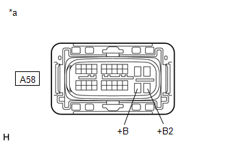
(b) Disconnect the A58 inverter with converter assembly connector.
Click here
| (c) Measure the resistance according to the value(s) in the table below. Standard Resistance:
|
|
(d) Connect the cable to the negative (-) auxiliary battery terminal.
(e) Turn the power switch on (IG).
(f) Measure the voltage according to the value(s) in the table below.
Standard Voltage:
| Tester Connection | Condition | Specified Condition |
|---|---|---|
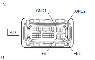
| A58-30 (+B) - Body ground | Power switch on (IG) | Same as auxiliary battery voltage |
| A58-31 (+B2) - Body ground | Power switch on (IG) | Same as auxiliary battery voltage |
NOTICE:
Turning the power switch on (IG) with the inverter with converter assembly connector disconnected causes other DTCs to be stored. Clear the DTCs after performing this inspection.
(g) Turn the power switch off.
(h) Disconnect the cable from the negative (-) auxiliary battery terminal.
(i) Reconnect the A58 inverter with converter assembly connector.
| NG | | REPAIR OR REPLACE POWER SOURCE CIRCUIT |
|
| 3. | CHECK HARNESS AND CONNECTOR (HYBRID VEHICLE CONTROL ECU - INVERTER WITH CONVERTER ASSEMBLY) |
CAUTION:
Be sure to wear insulated gloves.
(a) Check that the service plug grip is not installed.
NOTICE:
After removing the service plug grip, do not turn the power switch on (READY), unless instructed by the repair manual because this may cause a malfunction.
(b) Disconnect the A58 inverter with converter assembly connector.
(c) Disconnect the A61 hybrid vehicle control ECU connector.
| (d) Measure the resistance according to the value(s) in the table below. Standard Resistance (Check for Open):
Standard Resistance (Check for Short):
|
|
(e) Connect the cable to the negative (-) auxiliary battery terminal.
(f) Turn the power switch on (IG).
(g) Measure the voltage according to the value(s) in the table below.
Standard Voltage:
| Tester Connection | Condition | Specified Condition |
|---|---|---|
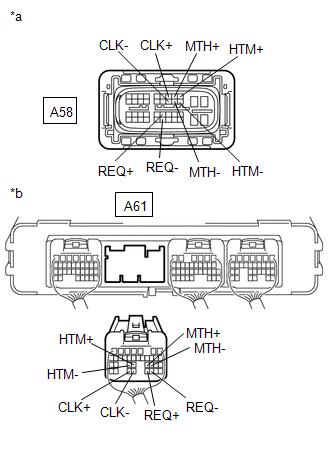
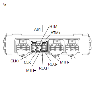
| A58-9 (HTM+) or A61-24 (HTM+) - Body ground | Power switch on (IG) | Below 1 V |
| A58-20 (HTM-) or A61-25 (HTM-) - Body ground | Power switch on (IG) | Below 1 V |
| A58-8 (MTH+) or A61-23 (MTH+) - Body ground | Power switch on (IG) | Below 1 V |
| A58-19 (MTH-) or A61-22 (MTH-) - Body ground | Power switch on (IG) | Below 1 V |
| A58-26 (REQ+) or A61-31(REQ+) - Body ground | Power switch on (IG) | Below 1 V |
| A58-37 (REQ-) or A61-30 (REQ-) - Body ground | Power switch on (IG) | Below 1 V |
| A58-7 (CLK+) or A61-33 (CLK+) - Body ground | Power switch on (IG) | Below 1 V |
| A58-18 (CLK-) or A61-32 (CLK-) - Body ground | Power switch on (IG) | Below 1 V |
NOTICE:
Turning the power switch on (IG) with the hybrid vehicle control ECU and inverter with converter assembly connectors disconnected causes other DTCs to be stored. Clear the DTCs after performing this inspection.
(h) Turn the power switch off.
(i) Disconnect the cable from the negative (-) auxiliary battery terminal.
(j) Reconnect the A61 hybrid vehicle control ECU connector.
(k) Reconnect the A58 inverter with converter assembly connector.
| NG | | REPAIR OR REPLACE HARNESS OR CONNECTOR |
|
| 4. | CHECK HYBRID VEHICLE CONTROL ECU |
(a) Disconnect the A61 hybrid vehicle control ECU connector.
| (b) Measure the resistance according to the value(s) in the table below. Standard Resistance:
|
|
(c) Reconnect the A61 hybrid vehicle control ECU connector.
| OK | | INVERTER LOW-VOLTAGE CIRCUIT NORMAL (PERFORM NEXT STEP FOR REFERENCED DTC) |
| NG | | REPLACE HYBRID VEHICLE CONTROL ECU |
| 5. | CHECK HARNESS AND CONNECTOR (INVERTER WITH CONVERTER ASSEMBLY - PCU FUSE) |
CAUTION:
Be sure to wear insulated gloves.
(a) Check that the service plug grip is not installed.
NOTICE:
After removing the service plug grip, do not turn the power switch on (READY), unless instructed by the repair manual because this may cause a malfunction.
(b) Disconnect the A58 inverter with converter assembly connector.
Click here
| (c) Measure the resistance according to the value(s) in the table below. Standard Resistance:
|
|
(d) Reconnect the A58 inverter with converter assembly connector.
| NG | | GO TO STEP 7 |
|
| 6. | REPLACE INVERTER WITH CONVERTER ASSEMBLY |
Click here
| NEXT | | REPLACE FUSE (PCU) |
| 7. | REPAIR OR REPLACE HARNESS OR CONNECTOR |
| NEXT | | REPLACE FUSE (PCU) |
READ NEXT:
 HV Battery High-voltage Line Circuit
DESCRIPTION The cause of the malfunction may be the HV battery high-voltage line circuit. Check the continuity in the high-voltage line from the HV battery to the inverter. Check the connection condit
Cooling System
DESCRIPTION The cause of the malfunction may be the cooling system. Check whether the grille is blocked, whether coolant is leaking, the HV radiator fan operating condition and whether coolant has fro
Hybrid Vehicle Control Ecu
ComponentsCOMPONENTS ILLUSTRATION *1 ECU INTEGRATION BOX RH *2 GLOVE COMPARTMENT DOOR ASSEMBLY *3 HYBRID VEHICLE CONTROL ECU *4 NO. 2 INSTRUMENT PANEL UNDER COVER SUB-ASSEMBLY
SEE MORE:
IG Power Supply Voltage (C1551)
DESCRIPTION The power steering ECU assembly distinguishes the power switch status as on (IG) or off through the IG power source circuit. DTC No. Detection Item DTC Detection Condition Trouble Area Warning Indicate Return-to-normal Condition Note C1551 IG Power Supply Voltage I
Removal
REMOVAL PROCEDURE 1. PRECAUTION Click here 2. REMOVE SERVICE PLUG GRIP Click here 3. DRAIN COOLANT (for Inverter Coolant) Click here 4. DISCONNECT WIRE HARNESS (a) Disconnect the 4 wire harness clamps from the inverter reserve tank assembly and inverter with converter assembly.
