Lexus NX: Side Satellite Sensor Bus Lost Communication (RH) (B1642,B1643,B1647,B1648)
DESCRIPTION
The circuit for the side collision sensor LH or RH is composed of the airbag ECU assembly, side airbag sensor assembly LH or RH and door side airbag sensor LH or RH.
The door side airbag sensor LH or RH and side airbag sensor assembly LH or RH detect impacts to the vehicle and send signals to the airbag ECU assembly to determine if the airbag should be deployed.
DTC B1642, B1643, B1647 or B1648 is stored when a malfunction is detected in the circuit for the side satellite sensor bus LH or RH.
| DTC No. | Detection Item | DTC Detection Condition | Trouble Area |
|---|---|---|---|
| B1642 | Side Satellite Sensor Bus Lost Communication (RH) | One of the following conditions is met:
|
|
| B1643 | Side Satellite Sensor Bus Initialization Error (RH) | One of the following conditions is met:
|
|
| B1647 | Side Satellite Sensor Bus Lost Communication (LH) | One of the following conditions is met:
|
|
| B1648 | Side Satellite Sensor Bus Initialization Error (LH) | One of the following conditions is met:
|
|
WIRING DIAGRAM
.png)
.png)
CAUTION / NOTICE / HINT
NOTICE:
-
After the power switch is turned off, there may be a waiting time before disconnecting the negative (-) auxiliary battery terminal.
Click here
.gif)
-
When disconnecting and reconnecting the auxiliary battery
Click here
HINT:
When disconnecting and reconnecting the auxiliary battery, there is an automatic learning function that completes learning when the respective system is used.
Click here
-
After replacing the airbag ECU assembly, refer to initialization.
Click here
PROCEDURE
| 1. | CHECK DTC |
(a) Turn the power switch off.
(b) Turn the power switch on (IG), and wait for at least 60 seconds.
(c) Check for DTCs.
Click here
HINT:
Codes other than DTC B1642, B1643, B1647 and B1648 may be output at this time, but they are not related to this check.
| DTC B1647 or B1648 is output | .gif) | GO TO STEP 11 |
| DTC B1642, B1643, B1647 and B1648 are not output | | USE SIMULATION METHOD TO CHECK |
|
.gif)
| 2. | CHECK CONNECTION OF CONNECTORS |
(a) Turn the power switch off.
(b) Disconnect the cable from the negative (-) auxiliary battery terminal, and wait for at least 90 seconds.
(c) Check that the connectors are properly connected to the airbag ECU assembly and side airbag sensor assembly RH.
| The connectors are not properly connected | | CONNECT CONNECTORS PROPERLY |
|
| 3. | CHECK CONNECTORS |
(a) Disconnect the connectors from the airbag ECU assembly and side airbag sensor assembly RH.
| (b) Check that the connectors (on the airbag ECU assembly side and side airbag sensor assembly RH side) are not damaged. |
|
| The connectors are deformed or damaged | | REPLACE FLOOR WIRE |
|
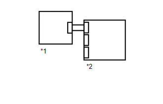
| 4. | CHECK FLOOR WIRE |
(a) Connect the cable to the negative (-) auxiliary battery terminal, and wait for at least 2 seconds.
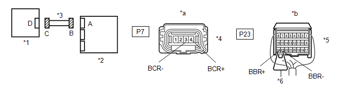
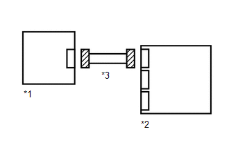
| *1 | Side Airbag Sensor Assembly RH | *2 | Airbag ECU Assembly |
| *3 | Floor Wire | *4 | Connector C |
| *5 | Connector B | *6 | Service Wire |
| *a | Front view of wire harness connector (to Side Airbag Sensor Assembly RH) | *b | Rear view of wire harness connector (to Airbag ECU Assembly) |
(b) Turn the power switch on (IG).
(c) Measure the voltage according to the value(s) in the table below.
Standard Voltage:
| Tester Connection | Switch Condition | Specified Condition |
|---|---|---|
| P7-4 (BCR+) - Body ground | Power switch on (IG) | Below 1 V |
| P7-3 (BCR-) - Body ground | Power switch on (IG) | Below 1 V |
(d) Turn the power switch off.
(e) Disconnect the cable from the negative (-) auxiliary battery terminal, and wait for at least 90 seconds.
(f) Using a service wire, connect terminals 24 (BBR+) and 23 (BBR-) of connector B.
NOTICE:
Do not forcibly insert the service wire into the terminals of the connector when connecting a service wire.
(g) Measure the resistance according to the value(s) in the table below.
Standard Resistance:
| Tester Connection | Condition | Specified Condition |
|---|---|---|
| P7-4 (BCR+) - P7-3 (BCR-) | Always | Below 1 Ω |
(h) Disconnect the service wire from connector B.
(i) Measure the resistance according to the value(s) in the table below.
Standard Resistance:
| Tester Connection | Condition | Specified Condition |
|---|---|---|
| P7-4 (BCR+) - P7-3 (BCR-) | Always | 1 MΩ or higher |
| P7-4 (BCR+) - Body ground | Always | 1 MΩ or higher |
| P7-3 (BCR-) - Body ground | Always | 1 MΩ or higher |
| NG | | REPLACE FLOOR WIRE |
|
| 5. | CHECK CONNECTION OF CONNECTOR |
(a) Check that the connector is properly connected to the door side airbag sensor RH.
| The connector is not properly connected | | CONNECT CONNECTOR PROPERLY |
|
| 6. | CHECK CONNECTOR |
(a) Disconnect the connector from the door side airbag sensor RH.
| (b) Check that the connector (on the door side airbag sensor RH side) is not damaged. |
|
| The connector is deformed or damaged | | REPLACE FRONT DOOR WIRE RH |
|
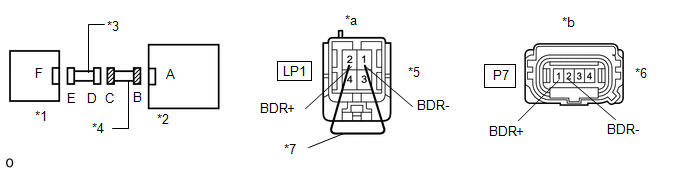
| 7. | CHECK DOOR SIDE AIRBAG SENSOR RH CIRCUIT |
(a) Connect the cable to the negative (-) auxiliary battery terminal, and wait for at least 2 seconds.
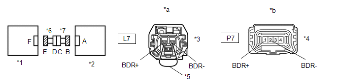
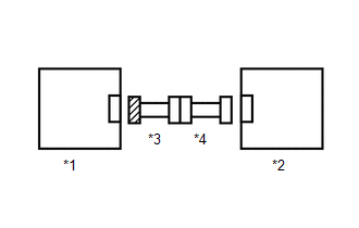
| *1 | Door Side Airbag Sensor RH | *2 | Side Airbag Sensor Assembly RH |
| *3 | Connector E | *4 | Connector B |
| *5 | Service Wire | *6 | Front Door Wire RH |
| *7 | Floor Wire | - | - |
| *a | Rear view of wire harness connector (to Door Side Airbag Sensor RH) | *b | Front view of wire harness connector (to Side Airbag Sensor Assembly RH) |
(b) Turn the power switch on (IG).
(c) Measure the voltage according to the value(s) in the table below.
Standard Voltage:
| Tester Connection | Switch Condition | Specified Condition |
|---|---|---|
| P7-1 (BDR+) - Body ground | Power switch on (IG) | Below 1 V |
| P7-2 (BDR-) - Body ground | Power switch on (IG) | Below 1 V |
(d) Turn the power switch off.
(e) Disconnect the cable from the negative (-) auxiliary battery terminal, and wait for at least 90 seconds.
(f) Using a service wire, connect terminals 2 (BDR+) and 1 (BDR-) of connector E.
NOTICE:
Do not forcibly insert the service wire into the terminals of the connector when connecting a service wire.
(g) Measure the resistance according to the value(s) in the table below.
Standard Resistance:
| Tester Connection | Condition | Specified Condition |
|---|---|---|
| P7-1 (BDR+) - P7-2 (BDR-) | Always | Below 1 Ω |
(h) Disconnect the service wire from connector E.
(i) Measure the resistance according to the value(s) in the table below.
Standard Resistance:
| Tester Connection | Condition | Specified Condition |
|---|---|---|
| P7-1 (BDR+) - P7-2 (BDR-) | Always | 1 MΩ or higher |
| P7-1 (BDR+) - Body ground | Always | 1 MΩ or higher |
| P7-2 (BDR-) - Body ground | Always | 1 MΩ or higher |
| NG | | GO TO STEP 10 |
|
| 8. | CHECK SIDE AIRBAG SENSOR ASSEMBLY RH |
| (a) Connect the connectors to the airbag ECU assembly and door side airbag sensor RH. |
|
(b) Interchange the side airbag sensor assembly RH with LH and connect the connectors to them.
(c) Connect the cable to the negative (-) auxiliary battery terminal, and wait for at least 2 seconds.
(d) Turn the power switch on (IG), and wait for at least 60 seconds.
(e) Clear the DTCs stored in memory.
Click here
(f) Turn the power switch off.
(g) Turn the power switch on (IG), and wait for at least 60 seconds.
(h) Check for DTCs.
Click here
HINT:
Codes other than DTC B1642, B1643, B1647 and B1648 may be output at this time, but they are not related to this check.
(i) Turn the power switch off.
(j) Disconnect the cable from the negative (-) auxiliary battery terminal, and wait for at least 90 seconds.
(k) Return the side airbag sensor assembly LH and RH to their original positions and connect the connectors to them.
| DTC B1647 or B1648 is output | | REPLACE SIDE AIRBAG SENSOR ASSEMBLY RH |
| DTC B1642, B1643, B1647 and B1648 are not output | | USE SIMULATION METHOD TO CHECK |
|
| 9. | CHECK DOOR SIDE AIRBAG SENSOR RH |
| (a) Interchange the door side airbag sensor RH with LH and connect the connectors to them. |
|
(b) Connect the cable to the negative (-) auxiliary battery terminal, and wait for at least 2 seconds.
(c) Turn the power switch on (IG), and wait for at least 60 seconds.
(d) Clear the DTCs stored in memory.
Click here
(e) Turn the power switch off.
(f) Turn the power switch on (IG), and wait for at least 60 seconds.
(g) Check for DTCs.
Click here
HINT:
Codes other than DTC B1642, B1643, B1647 and B1648 may be output at this time, but they are not related to this check.
(h) Turn the power switch off.
(i) Disconnect the cable from the negative (-) auxiliary battery terminal, and wait for at least 90 seconds.
(j) Return the door side airbag sensor LH and RH to their original positions and connect the connectors to them.
| DTC B1647 or B1648 is output | | REPLACE DOOR SIDE AIRBAG SENSOR RH |
| DTC B1642 or B1643 is output | | REPLACE AIRBAG ECU ASSEMBLY |
| DTC B1642, B1643, B1647 and B1648 are not output | | USE SIMULATION METHOD TO CHECK |
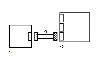
| 10. | CHECK FLOOR WIRE |
(a) Disconnect the floor wire connector from the front door wire RH.
| *1 | Door Side Airbag Sensor RH | *2 | Side Airbag Sensor Assembly RH |
| *3 | Front Door Wire RH | *4 | Floor Wire |
| *5 | Connector C | *6 | Connector B |
| *7 | Service Wire | - | - |
| *a | Front view of wire harness connector (to Front Door Wire RH) | *b | Front view of wire harness connector (to Side Airbag Sensor Assembly RH) |
(b) Connect the cable to the negative (-) auxiliary battery terminal, and wait for at least 2 seconds.
(c) Turn the power switch on (IG).
(d) Measure the voltage according to the value(s) in the table below.
Standard Voltage:
| Tester Connection | Switch Condition | Specified Condition |
|---|---|---|
| P7-1 (BDR+) - Body ground | Power switch on (IG) | Below 1 V |
| P7-2 (BDR-) - Body ground | Power switch on (IG) | Below 1 V |
(e) Turn the power switch off.
(f) Disconnect the cable from the negative (-) auxiliary battery terminal, and wait for at least 90 seconds.
(g) Using a service wire, connect terminals 2 (BDR+) and 1 (BDR-) of connector C.
NOTICE:
Do not forcibly insert the service wire into the terminals of the connector when connecting a service wire.
(h) Measure the resistance according to the value(s) in the table below.
Standard Resistance:
| Tester Connection | Condition | Specified Condition |
|---|---|---|
| P7-1 (BDR+) - P7-2 (BDR-) | Always | Below 1 Ω |
(i) Disconnect the service wire from connector C.
(j) Measure the resistance according to the value(s) in the table below.
Standard Resistance:
| Tester Connection | Condition | Specified Condition |
|---|---|---|
| P7-1 (BDR+) - P7-2 (BDR-) | Always | 1 MΩ or higher |
| P7-1 (BDR+) - Body ground | Always | 1 MΩ or higher |
| P7-2 (BDR-) - Body ground | Always | 1 MΩ or higher |
| OK | | REPLACE FRONT DOOR WIRE RH |
| NG | | REPLACE FLOOR WIRE |
| 11. | CHECK CONNECTION OF CONNECTORS |
(a) Turn the power switch off.
(b) Disconnect the cable from the negative (-) auxiliary battery terminal, and wait for at least 90 seconds.
(c) Check that the connectors are properly connected to the airbag ECU assembly and side airbag sensor assembly LH.
| The connectors are not properly connected | | CONNECT CONNECTORS PROPERLY |
|
| 12. | CHECK CONNECTORS |
(a) Disconnect the connectors from the airbag ECU assembly and side airbag sensor assembly LH.
| (b) Check that the connectors (on the airbag ECU assembly side and side airbag sensor assembly LH side) are not damaged. |
|
| The connectors are deformed or damaged | | REPLACE NO. 2 FLOOR WIRE |
|
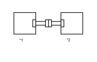
| 13. | CHECK NO. 2 FLOOR WIRE |
(a) Connect the cable to the negative (-) auxiliary battery terminal, and wait for at least 2 seconds.
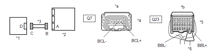
| *1 | Side Airbag Sensor Assembly LH | *2 | Airbag ECU Assembly |
| *3 | No. 2 Floor Wire | *4 | Connector C |
| *5 | Connector B | *6 | Service Wire |
| *a | Front view of wire harness connector (to Side Airbag Sensor Assembly LH) | *b | Rear view of wire harness connector (to Airbag ECU Assembly) |
(b) Turn the power switch on (IG).
(c) Measure the voltage according to the value(s) in the table below.
Standard Voltage:
| Tester Connection | Switch Condition | Specified Condition |
|---|---|---|
| Q7-4 (BCL+) - Body ground | Power switch on (IG) | Below 1 V |
| Q7-3 (BCL-) - Body ground | Power switch on (IG) | Below 1 V |
(d) Turn the power switch off.
(e) Disconnect the cable from the negative (-) auxiliary battery terminal, and wait for at least 90 seconds.
(f) Using a service wire, connect terminals 17 (BBL+) and 18 (BBL-) of connector B.
NOTICE:
Do not forcibly insert the service wire into the terminals of the connector when connecting a service wire.
(g) Measure the resistance according to the value(s) in the table below.
Standard Resistance:
| Tester Connection | Condition | Specified Condition |
|---|---|---|
| Q7-4 (BCL+) - Q7-3 (BCL-) | Always | Below 1 Ω |
(h) Disconnect the service wire from connector B.
(i) Measure the resistance according to the value(s) in the table below.
Standard Resistance:
| Tester Connection | Condition | Specified Condition |
|---|---|---|
| Q7-4 (BCL+) - Q7-3 (BCL-) | Always | 1 MΩ or higher |
| Q7-4 (BCL+) - Body ground | Always | 1 MΩ or higher |
| Q7-3 (BCL-) - Body ground | Always | 1 MΩ or higher |
| NG | | REPLACE NO. 2 FLOOR WIRE |
|
| 14. | CHECK CONNECTION OF CONNECTOR |
(a) Check that the connector is properly connected to the door side airbag sensor LH.
| The connector is not properly connected | | CONNECT CONNECTOR PROPERLY |
|
| 15. | CHECK CONNECTOR |
(a) Disconnect the connector from the door side airbag sensor LH.
| (b) Check that the connector (on the door side airbag sensor LH side) is not damaged. |
|
| The connector is deformed or damaged | | REPLACE FRONT DOOR WIRE LH |
|
| 16. | CHECK DOOR SIDE AIRBAG SENSOR LH CIRCUIT |
(a) Connect the cable to the negative (-) auxiliary battery terminal, and wait for at least 2 seconds.
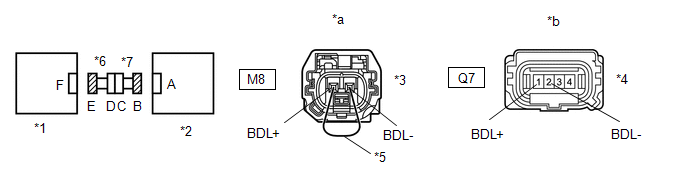
| *1 | Door Side Airbag Sensor LH | *2 | Side Airbag Sensor Assembly LH |
| *3 | Connector E | *4 | Connector B |
| *5 | Service Wire | *6 | Front Door Wire LH |
| *7 | No. 2 Floor Wire | - | - |
| *a | Rear view of wire harness connector (to Door Side Airbag Sensor LH) | *b | Front view of wire harness connector (to Side Airbag Sensor Assembly LH) |
(b) Turn the power switch on (IG).
(c) Measure the voltage according to the value(s) in the table below.
Standard Voltage:
| Tester Connection | Switch Condition | Specified Condition |
|---|---|---|
| Q7-1 (BDL+) - Body ground | Power switch on (IG) | Below 1 V |
| Q7-2 (BDL-) - Body ground | Power switch on (IG) | Below 1 V |
(d) Turn the power switch off.
(e) Disconnect the cable from the negative (-) auxiliary battery terminal, and wait for at least 90 seconds.
(f) Using a service wire, connect terminals 2 (BDL+) and 1 (BDL-) of connector E.
NOTICE:
Do not forcibly insert the service wire into the terminals of the connector when connecting a service wire.
(g) Measure the resistance according to the value(s) in the table below.
Standard Resistance:
| Tester Connection | Condition | Specified Condition |
|---|---|---|
| Q7-1 (BDL+) - Q7-2 (BDL-) | Always | Below 1 Ω |
(h) Disconnect the service wire from connector E.
(i) Measure the resistance according to the value(s) in the table below.
Standard Resistance:
| Tester Connection | Condition | Specified Condition |
|---|---|---|
| Q7-1 (BDL+) - Q7-2 (BDL-) | Always | 1 MΩ or higher |
| Q7-1 (BDL+) - Body ground | Always | 1 MΩ or higher |
| Q7-2 (BDL-) - Body ground | Always | 1 MΩ or higher |
| NG | | GO TO STEP 19 |
|
| 17. | CHECK SIDE AIRBAG SENSOR ASSEMBLY LH |
| (a) Connect the connectors to the airbag ECU assembly and door side airbag sensor LH. |
|
(b) Interchange the side airbag sensor assembly LH with RH and connect the connectors to them.
(c) Connect the cable to the negative (-) auxiliary battery terminal, and wait for at least 2 seconds.
(d) Turn the power switch on (IG), and wait for at least 60 seconds.
(e) Clear the DTCs stored in memory.
Click here
(f) Turn the power switch off.
(g) Turn the power switch on (IG), and wait for at least 60 seconds.
(h) Check for DTCs.
Click here
HINT:
Codes other than DTC B1642, B1643, B1647 and B1648 may be output at this time, but they are not related to this check.
(i) Turn the power switch off.
(j) Disconnect the cable from the negative (-) auxiliary battery terminal, and wait for at least 90 seconds.
(k) Return the side airbag sensor assembly RH and LH to their original positions and connect the connectors to them.
| DTC B1642 or B1643 is output | | REPLACE SIDE AIRBAG SENSOR ASSEMBLY LH |
| DTC B1642, B1643, B1647 and B1648 are not output | | USE SIMULATION METHOD TO CHECK |
|
| 18. | CHECK DOOR SIDE AIRBAG SENSOR LH |
| (a) Interchange the door side airbag sensor LH with RH and connect the connectors to them. |
|
(b) Connect the cable to the negative (-) auxiliary battery terminal, and wait for at least 2 seconds.
(c) Turn the power switch on (IG), and wait for at least 60 seconds.
(d) Clear the DTCs stored in memory.
Click here
(e) Turn the power switch off.
(f) Turn the power switch on (IG), and wait for at least 60 seconds.
(g) Check for DTCs.
Click here
HINT:
Codes other than DTC B1642, B1643, B1647 and B1648 may be output at this time, but they are not related to this check.
(h) Turn the power switch off.
(i) Disconnect the cable from the negative (-) auxiliary battery terminal, and wait for at least 90 seconds.
(j) Return the door side airbag sensor RH and LH to their original positions and connect the connectors to them.
| DTC B1642 or B1643 is output | | REPLACE DOOR SIDE AIRBAG SENSOR LH |
| DTC B1647 or B1648 is output | | REPLACE AIRBAG ECU ASSEMBLY |
| DTC B1642, B1643, B1647 and B1648 are not output | | USE SIMULATION METHOD TO CHECK |
| 19. | CHECK NO. 2 FLOOR WIRE |
(a) Disconnect the No. 2 floor wire connector from the front door wire LH.
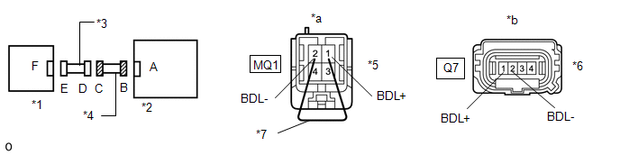
| *1 | Door Side Airbag Sensor LH | *2 | Side Airbag Sensor Assembly LH |
| *3 | Front Door Wire LH | *4 | No. 2 Floor Wire |
| *5 | Connector C | *6 | Connector B |
| *7 | Service Wire | - | - |
| *a | Front view of wire harness connector (to Front Door Wire LH) | *b | Front view of wire harness connector (to Side Airbag Sensor Assembly LH) |
(b) Connect the cable to the negative (-) auxiliary battery terminal, and wait for at least 2 seconds.
(c) Turn the power switch on (IG).
(d) Measure the voltage according to the value(s) in the table below.
Standard Voltage:
| Tester Connection | Switch Condition | Specified Condition |
|---|---|---|
| Q7-1 (BDL+) - Body ground | Power switch on (IG) | Below 1 V |
| Q7-2 (BDL-) - Body ground | Power switch on (IG) | Below 1 V |
(e) Turn the power switch off.
(f) Disconnect the cable from the negative (-) auxiliary battery terminal, and wait for at least 90 seconds.
(g) Using a service wire, connect terminals 1 (BDL+) and 2 (BDL-) of connector C.
NOTICE:
Do not forcibly insert the service wire into the terminals of the connector when connecting a service wire.
(h) Measure the resistance according to the value(s) in the table below.
Standard Resistance:
| Tester Connection | Condition | Specified Condition |
|---|---|---|
| Q7-1 (BDL+) - Q7-2 (BDL-) | Always | Below 1 Ω |
(i) Disconnect the service wire from connector C.
(j) Measure the resistance according to the value(s) in the table below.
Standard Resistance:
| Tester Connection | Condition | Specified Condition |
|---|---|---|
| Q7-1 (BDL+) - Q7-2 (BDL-) | Always | 1 MΩ or higher |
| Q7-1 (BDL+) - Body ground | Always | 1 MΩ or higher |
| Q7-2 (BDL-) - Body ground | Always | 1 MΩ or higher |
| OK | | REPLACE FRONT DOOR WIRE LH |
| NG | | REPLACE NO. 2 FLOOR WIRE |
READ NEXT:
 Occupant Classification System Malfunction (B1650)
DESCRIPTION The occupant classification system circuit consists of the airbag ECU assembly and occupant detection ECU. If the airbag ECU assembly receives signals from the occupant detection ECU, it d
Driver Side Seat Position Sensor (B1653)
DESCRIPTION The seat position airbag sensor circuit consists of the airbag ECU assembly and seat position airbag sensor. DTC B1653 is stored when a malfunction is detected in the seat position airbag
Seat Belt Buckle Switch (LH) (B1656)
DESCRIPTION The seat belt buckle switch LH circuit consists of the airbag ECU assembly and front seat inner belt assembly LH. DTC B1656 is stored when a malfunction is detected in the seat belt buckle
SEE MORE:
Destination Information Undefined (C1AB8)
DESCRIPTION This DTC is stored when correct destination information is not sent from the main body ECU (multiplex network body ECU) and destination information cannot be confirmed after a blind spot monitor sensor has been replaced. DTC No. Detection Item DTC Detection Condition Trouble Are
Problem Symptoms Table
PROBLEM SYMPTOMS TABLE HINT:
Use the table below to help determine the cause of the problem symptom. If multiple suspected areas are listed, the potential causes of the symptoms are listed in order of probability in the "Suspected Area" column of the table. Check each symptom by checking the susp
