Lexus NX: Speaker Circuit
DESCRIPTION
If there is a short in a speaker circuit, the stereo component amplifier assembly detects it and stops output to the speakers.
As a result, sound cannot be heard from the speakers even if there is no malfunction in the stereo component amplifier assembly, DCM (telematics transceiver)* or speakers.
- *: w/ Manual (SOS) Switch
WIRING DIAGRAM
.png)
CAUTION / NOTICE / HINT
NOTICE:
When replacing the DCM (telematics transceiver), make sure to replace it with a new one (w/ Manual [SOS] Switch).
HINT:
Depending on the parts that are replaced during vehicle inspection or maintenance, performing initialization, registration or calibration may be needed. Refer to Precaution for Audio and Visual System.
Click here .gif)
PROCEDURE
| 1. | CHECK HARNESS AND CONNECTOR (SPEAKER CIRCUIT) |
-
*1: for LH Side
*2: for RH Side
*3: w/ Manual (SOS) Switch
(a) Disconnect the P32 stereo component amplifier assembly connector.
(b) Disconnect the M9*1 and/or L9*2 front No. 1 speaker assembly connector.
(c) Disconnect the J9*1 and/or J8*2 front No. 2 speaker assembly connector.
(d) Disconnect the O6*1 and/or N5*2 rear No. 2 speaker assembly connector.
(e) Disconnect the O5*1 and/or N6*2 rear speaker assembly connector.
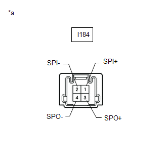
(f) Disconnect the I184 DCM (telematics transceiver) connector.*3
(g) Measure the resistance according to the value(s) in the table below.
Standard Resistance:
for LH Side| Tester Connection | Condition | Specified Condition |
|---|---|---|
| P32-4 (WFL+) - M9-1 | Always | Below 1 Ω |
| P32-19 (WFL-) - M9-2 | Always | Below 1 Ω |
| P32-12 (FL+) - J9-4 | Always | Below 1 Ω |
| P32-27 (FL-) - J9-2 | Always | Below 1 Ω |
| P32-8 (RL+) - O6-3 (+TW) | Always | Below 1 Ω |
| P32-23 (RL-) - O6-1 (-TW) | Always | Below 1 Ω |
| O6-4 (+) - O5-1 | Always | Below 1 Ω |
| O6-2 (-) - O5-2 | Always | Below 1 Ω |
| P32-4 (WFL+) - Body ground | Always | 10 kΩ or higher |
| P32-19 (WFL-) - Body ground | Always | 10 kΩ or higher |
| P32-12 (FL+) - Body ground | Always | 10 kΩ or higher |
| P32-27 (FL-) - Body ground | Always | 10 kΩ or higher |
| P32-8 (RL+) - Body ground | Always | 10 kΩ or higher |
| P32-23 (RL-) - Body ground | Always | 10 kΩ or higher |
| O6-4 (+) - Body ground | Always | 10 kΩ or higher |
| O6-2 (-) - Body ground | Always | 10 kΩ or higher |
| Tester Connection | Condition | Specified Condition |
|---|---|---|
| P32-5 (WFR+) - I184-1 (SPI+) | Always | Below 1 Ω |
| P32-20 (WFR-) - I184-2 (SPI-) | Always | Below 1 Ω |
| I184-3 (SPO+) - L9-1 | Always | Below 1 Ω |
| I184-4 (SPO-) - L9-2 | Always | Below 1 Ω |
| P32-13 (FR+) - J8-4 | Always | Below 1 Ω |
| P32-28 (FR-) - J8-2 | Always | Below 1 Ω |
| P32-9 (RR+) - N5-3 (+TW) | Always | Below 1 Ω |
| P32-24 (RR-) - N5-1 (-TW) | Always | Below 1 Ω |
| N5-4 (+) - N6-1 | Always | Below 1 Ω |
| N5-2 (-) - N6-2 | Always | Below 1 Ω |
| P32-5 (WFR+) - Body ground | Always | 10 kΩ or higher |
| P32-20 (WFR-) - Body ground | Always | 10 kΩ or higher |
| I184-3 (SPO+) - Body ground | Always | 10 kΩ or higher |
| I184-4 (SPO-) - Body ground | Always | 10 kΩ or higher |
| P32-13 (FR+) - Body ground | Always | 10 kΩ or higher |
| P32-28 (FR-) - Body ground | Always | 10 kΩ or higher |
| P32-9 (RR+) - Body ground | Always | 10 kΩ or higher |
| P32-24 (RR-) - Body ground | Always | 10 kΩ or higher |
| N5-4 (+) - Body ground | Always | 10 kΩ or higher |
| N5-2 (-) - Body ground | Always | 10 kΩ or higher |
| Tester Connection | Condition | Specified Condition |
|---|---|---|
| P32-5 (WFR+) - L9-1 | Always | Below 1 Ω |
| P32-20 (WFR-) - L9-2 | Always | Below 1 Ω |
| P32-13 (FR+) - J8-4 | Always | Below 1 Ω |
| P32-28 (FR-) - J8-2 | Always | Below 1 Ω |
| P32-9 (RR+) - N5-3 (+TW) | Always | Below 1 Ω |
| P32-24 (RR-) - N5-1 (-TW) | Always | Below 1 Ω |
| N5-4 (+) - N6-1 | Always | Below 1 Ω |
| N5-2 (-) - N6-2 | Always | Below 1 Ω |
| P32-5 (WFR+) - Body ground | Always | 10 kΩ or higher |
| P32-20 (WFR-) - Body ground | Always | 10 kΩ or higher |
| P32-13 (FR+) - Body ground | Always | 10 kΩ or higher |
| P32-28 (FR-) - Body ground | Always | 10 kΩ or higher |
| P32-9 (RR+) - Body ground | Always | 10 kΩ or higher |
| P32-24 (RR-) - Body ground | Always | 10 kΩ or higher |
| N5-4 (+) - Body ground | Always | 10 kΩ or higher |
| N5-2 (-) - Body ground | Always | 10 kΩ or higher |
| NG | .gif) | REPAIR OR REPLACE HARNESS OR CONNECTOR |
|
.gif)
| 2. | INSPECT FRONT NO. 1 SPEAKER ASSEMBLY |
(a) Remove the front No. 1 speaker assembly.
Click here
(b) Inspect the front No. 1 speaker assembly.
Click here
| NG | | REPLACE FRONT NO. 1 SPEAKER ASSEMBLY |
|
| 3. | INSPECT FRONT NO. 2 SPEAKER ASSEMBLY |
(a) Remove the front No. 2 speaker assembly.
Click here
(b) Inspect the front No. 2 speaker assembly.
Click here
| NG | | REPLACE FRONT NO. 2 SPEAKER ASSEMBLY |
|
| 4. | INSPECT REAR SPEAKER ASSEMBLY |
(a) Remove the rear speaker assembly.
Click here
(b) Inspect the rear speaker assembly.
Click here
| NG | | REPLACE REAR SPEAKER ASSEMBLY |
|
| 5. | CHECK VEHICLE TYPE |
(a) Check the vehicle type.
| Result | Proceed to |
|---|---|
| w/ Manual (SOS) Switch | A |
| w/o Manual (SOS) Switch | B |
| B | | GO TO STEP 7 |
|
| 6. | INSPECT DCM (TELEMATICS TRANSCEIVER) (SPO+, SPO-, SPI+, SPI-) |
(a) Remove the DCM (telematics transceiver).
Click here
| (b) Measure the resistance according to the value(s) in the table below. Standard Resistance:
|
|
| NG | | REPLACE DCM (TELEMATICS TRANSCEIVER) |
|
| 7. | CHECK REAR NO. 2 SPEAKER ASSEMBLY |
(a) Replace the rear No. 2 speaker assembly with a new or known good one.
Click here
(b) Check the malfunction disappears.
OK:
Malfunction disappears.
HINT:
- Connect all the connectors to the rear No. 2 speaker assemblies that were disconnected.
- When there is a possibility that either the right or left front speaker is defective, inspect by interchanging the right one with the left one.
- Perform the above inspection on both the LH and RH sides.
| OK | | END (REAR NO. 2 SPEAKER ASSEMBLY IS DEFECTIVE) |
| NG | | REPLACE STEREO COMPONENT AMPLIFIER ASSEMBLY |
READ NEXT:
 Sound Signal Circuit between Radio Receiver and Stereo Component Amplifier
DESCRIPTION The radio receiver assembly sends a sound signal to the stereo component amplifier assembly via this circuit. The sound signal that is sent is amplified by the stereo component amplifier a
Sound Signal Circuit between Radio Receiver and Stereo Jack Adapter
DESCRIPTION The No. 1 stereo jack adapter assembly sends the sound signal from an external device to the radio receiver assembly via this circuit. The sound signal that has been sent is amplified by t
Data Signal Circuit between Radio Receiver and Stereo Jack Adapter
DESCRIPTION The No. 1 stereo jack adapter assembly sends the sound data signal or image data signal from a USB device to the radio receiver assembly via this circuit. WIRING DIAGRAM PROCEDURE 1.
SEE MORE:
Problem Symptoms Table
PROBLEM SYMPTOMS TABLE NOTICE:
Use the table below to help determine the cause of problem symptoms. If multiple suspected areas are listed, the potential causes of the symptoms are listed in order of probability in the "Suspected Area" column of the table. Check each symptom by checking the suspe
DC / DC Converter Status Circuit High Input (P0A10-592)
DESCRIPTION Refer to the description for DTC P0A09-591. Click here DTC No. Detection Item DTC Detection Condition Trouble Area MIL Warning Indicate P0A10-592 DC / DC Converter Status Circuit High Input Short to +B in the DC/DC converter VLO signal line (1 trip detection logic)
