Lexus NX: Components
Lexus NX Service Manual / Vehicle Exterior / Lighting (ext) / Rear Combination Light Assembly / Components
COMPONENTS
ILLUSTRATION
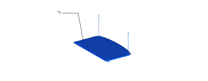
| *1 | TONNEAU COVER ASSEMBLY | - | - |
ILLUSTRATION
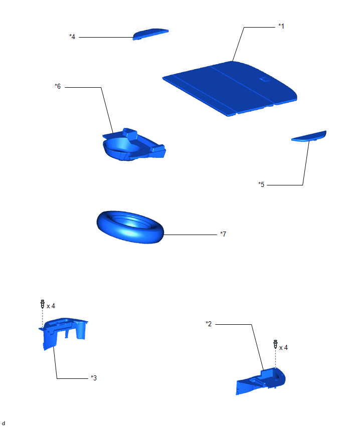
| *1 | DECK BOARD ASSEMBLY | *2 | DECK FLOOR BOX LH |
| *3 | DECK FLOOR BOX RH | *4 | NO. 2 DECK BOARD SUB-ASSEMBLY |
| *5 | NO. 3 DECK BOARD SUB-ASSEMBLY | *6 | REAR DECK FLOOR BOX |
| *7 | SPARE TIRE | - | - |
ILLUSTRATION
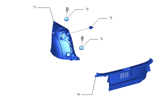
| *1 | DECK TRIM SIDE PANEL ASSEMBLY LH | *2 | LUGGAGE HOLD BELT STRIKER ASSEMBLY |
| *3 | NO. 1 LUGGAGE COMPARTMENT TRIM HOOK | *4 | REAR FLOOR FINISH PLATE |
ILLUSTRATION
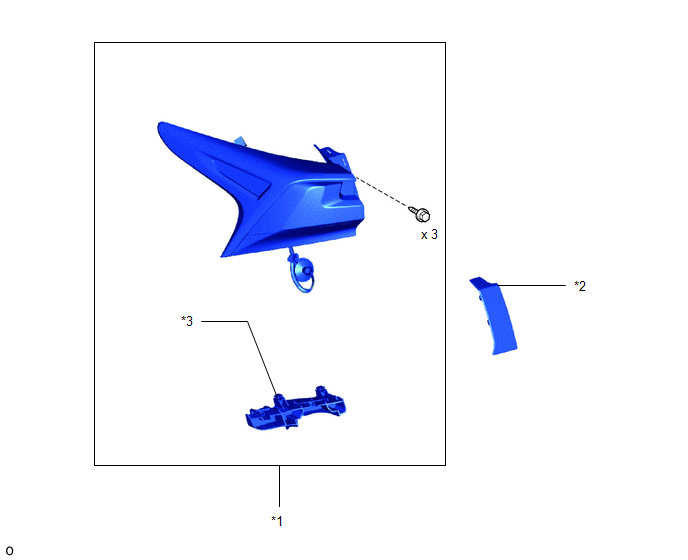
| *1 | REAR COMBINATION LIGHT ASSEMBLY LH | *2 | REAR COMBINATION LIGHT COVER LH |
| *3 | REAR COMBINATION LIGHT RETAINER LH | - | - |
ILLUSTRATION
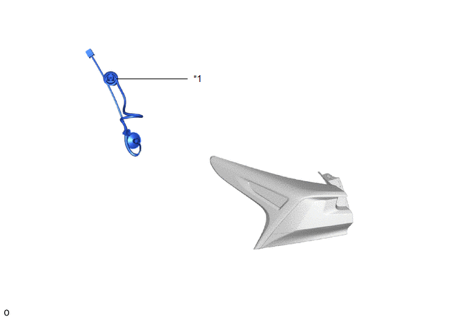
| *1 | REAR COMBINATION LIGHT SOCKET AND WIRE SUB-ASSEMBLY LH | - | - |
READ NEXT:
 Removal
REMOVAL CAUTION / NOTICE / HINT HINT:
Use the same procedure for the RH and LH sides.
The procedure described below is for the LH side.
PROCEDURE 1. REMOVE REAR BUMPER ASSEMBLY Click here 2.
Disassembly
DISASSEMBLY PROCEDURE 1. PRECAUTION NOTICE:
Be sure to read Precaution thoroughly before servicing.
Click here
Handle components indoors as much as possible to prevent foreign matter from enter
Inspection
INSPECTION PROCEDURE 1. INSPECT REAR COMBINATION LIGHT ASSEMBLY LH (a) Apply battery voltage to the connector and check the light illumination condition. OK: Battery Connection Specified Cond
SEE MORE:
Inspection
INSPECTION PROCEDURE 1. INSPECT INTEGRATION CONTROL AND PANEL ASSEMBLY (VSC OFF SWITCH) (a) Measure the resistance according to the value(s) in the table below. Standard Resistance: Tester Connection Condition Specified Condition 4 (+) - 1 (GND) Switch not pushed 10 kΩ or higher
Data List / Active Test
DATA LIST / ACTIVE TEST READ DATA LIST HINT: Using the Techstream to read the Data List allows the values or states of switches, sensors, actuators and other items to be read without removing any parts. This non-intrusive inspection can be very useful because intermittent conditions or signals may b
© 2016-2026 Copyright www.lexunx.com
