Lexus NX: Starter Relay Circuit High (P0617-142)
DESCRIPTION
| DTC No. | Detection Item | DTC Detection Condition | Trouble Area | MIL | Warning Indicate |
|---|---|---|---|---|---|
| P0617-142 | Starter Relay Circuit High | An ST signal from the hybrid vehicle control ECU is on when the power switch is off. (2 trip detection logic) |
| Does not come on | Master Warning Light: Comes on |
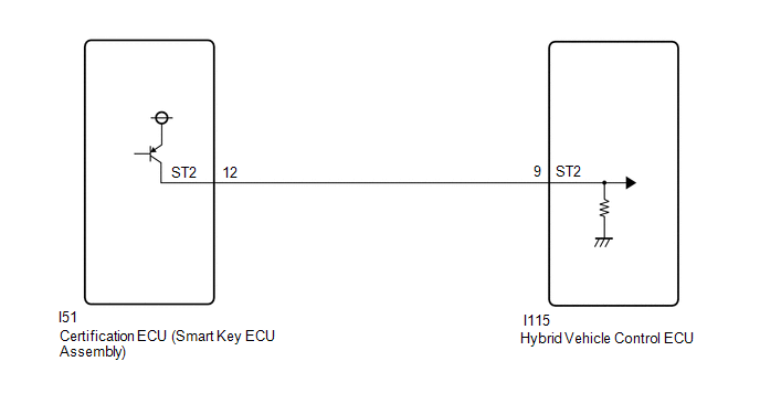
WIRING DIAGRAM
CAUTION / NOTICE / HINT
HINT:
After the repair, clear the DTCs and perform the following procedure to check that DTCs are not output.
- Turn the power switch off and wait for 5 seconds or more.
PROCEDURE
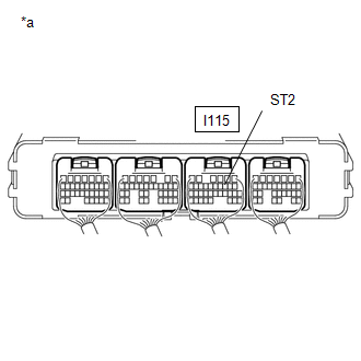
| 1. | CHECK CONNECTOR CONNECTION CONDITION (HYBRID VEHICLE CONTROL ECU CONNECTOR) |
Click here .gif)
| NG | .gif) | CONNECT SECURELY |
|
.gif)
| 2. | CHECK CONNECTOR CONNECTION CONDITION (CERTIFICATION ECU [SMART KEY ECU ASSEMBLY]) |
(a) Check the connector connection condition of the certification ECU (smart key ECU assembly).
HINT:
Refer to the Service Bulletin for the installation position.
OK:
The connector is connected securely and there are no contact problems.
| NG | | CONNECT SECURELY |
|
| 3. | CHECK HARNESS AND CONNECTOR (ST2 TERMINAL VOLTAGE) |
| (a) Turn the power switch off. |
|
(b) Measure the voltage according to the value(s) in the table below.
Standard Voltage:
| Tester Connection | Condition | Specified Condition |
|---|---|---|
| I115-9 (ST2) - Body ground | Power switch off | Below 1 V |
| OK | | REPLACE HYBRID VEHICLE CONTROL ECU |
|
| 4. | CHECK HARNESS AND CONNECTOR (HYBRID VEHICLE CONTROL ECU - CERTIFICATION ECU [SMART KEY ECU ASSEMBLY]) |
| (a) Disconnect the I51 certification ECU (smart key ECU assembly) connector. |
|
(b) Measure the voltage according to the value(s) in the table below.
Standard Voltage:
| Tester Connection | Condition | Specified Condition |
|---|---|---|
| I115-9 (ST2) - Body ground | Power switch off | Below 1 V |
(c) Reconnect the I51 certification ECU (smart key ECU assembly) connector.
| OK | | REPLACE CERTIFICATION ECU (SMART KEY ECU ASSEMBLY) |
| NG | | REPAIR OR REPLACE HARNESS OR CONNECTOR |
READ NEXT:
 Internal Control Module EEPROM Error (P062F-143,P062F-165)
DESCRIPTION DTC No. Detection Item DTC Detection Condition Trouble Area MIL Warning Indicate P062F-143 Internal Control Module EEPROM Error ECU internal malfunction (EEPROM error)
Internal Control Module EEPROM Error (P062F-489)
DESCRIPTION The hybrid vehicle control ECU monitors its internal operation and will store the DTC when it detects an internal malfunction. DTC No. Detection Item DTC Detection Condition Troub
Sensor Power Supply "A" Circuit / Open (P06B0-163,P06D6-511,P06E6-164,P0A1B-786,P0A1B-794,P1C2B-192,P1C73-512,P1CA7-193,P3134-661)
DESCRIPTION The MG ECU, which is built into the inverter with converter assembly, monitors its internal operation and will store DTCs if the system is malfunctioning. If any of the following DTCs are
SEE MORE:
Precaution
PRECAUTION PRECAUTION FOR DISCONNECTING CABLE FROM NEGATIVE AUXILIARY BATTERY TERMINAL NOTICE:
When disconnecting the cable from the negative (-) auxiliary battery terminal, initialize the some systems after the cable is reconnected.
Click here
If the auxiliary battery has been discharged and
Main Body ECU Vehicle Information Reading/Writing Process Malfunction (B15F6)
DESCRIPTION This DTC is stored when items controlled by the main body ECU (multiplex network body ECU) cannot be customized via the audio and visual system vehicle customization screen. HINT: The main body ECU (multiplex network body ECU) controls the items for the following systems that are customi
