Lexus NX: Stop Light Switch Circuit (P0571)
DESCRIPTION
When the brakes are applied by the dynamic radar cruise control system, the skid control ECU (brake booster with master cylinder assembly) operates the stop light control ECU assembly to illuminate the stop lights.
-
Detection Condition1
- If the hybrid vehicle control ECU receives a signal from the skid control ECU (brake booster with master cylinder assembly) indicating a malfunction of the stop light switch assembly, DTC P0571 is stored.
When the brake pedal is depressed, the stop light switch assembly outputs a signal to the hybrid vehicle control ECU. The hybrid vehicle control ECU uses this signal to control cancellation of vehicle speed by the dynamic radar cruise control.
-
Detection Condition2
- When the hybrid vehicle control ECU determines that terminals STP and ST1- of the stop light switch assembly are both less than 1 V, DTC P0571 is stored.
| DTC No. | Detection Item | DTC Detection Condition | Trouble Area | DTC Output from |
|---|---|---|---|---|
| P0571 | Stop Light Switch Circuit | Detection Condition1
Detection Condition2
| Detection Condition1
Detection Condition2
| Hybrid vehicle control ECU |
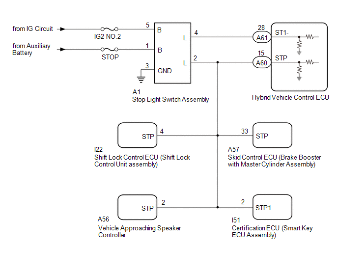
WIRING DIAGRAM
CAUTION / NOTICE / HINT
NOTICE:
- Inspect the fuses for circuits related to this system before performing the following procedure.
- Before replacing the hybrid vehicle control ECU, refer to Service Bulletin.
PROCEDURE
| 1. | CHECK ELECTRONICALLY CONTROLLED BRAKE SYSTEM |
(a) Check the electronically controlled brake system.
Click here .gif)
HINT:
When P0571 is detected by the dynamic radar cruise control system, DTCs may also be detected in the electronically controlled brake system. Therefore, check the electronically controlled brake system first when P0571 is detected.
| NG | .gif) | END |
|
.gif)
| 2. | CHECK HARNESS AND CONNECTOR (STOP LIGHT SWITCH ASSEMBLY - BATTERY AND BODY GROUND) |
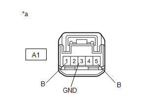
| (a) Disconnect the stop light switch assembly connector. |
|
(b) Measure the resistance according to the value(s) in the table below.
Standard Resistance:
| Tester Connection | Condition | Specified Condition |
|---|---|---|
| A1-3 (GND) - Body ground | Always | Below 1 Ω |
(c) Measure the voltage according to the value(s) in the table below.
Standard Voltage:
| Tester Connection | Condition | Specified Condition |
|---|---|---|
| A1-1 (B) - Body ground | Always | 11 to 14 V |
| A1-5 (B) - Body ground | Power switch on (IG) | 11 to 14 V |
| A1-5 (B) - Body ground | Power switch off | Below 1 V |
(d) Connect the stop light switch assembly connector.
| NG | | REPAIR OR REPLACE HARNESS OR CONNECTOR |
|
| 3. | INSPECT STOP LIGHT SWITCH ASSEMBLY |
(a) Inspect the stop light switch assembly.
Click here
| NG | | REPLACE STOP LIGHT SWITCH ASSEMBLY |
|
| 4. | CHECK HARNESS AND CONNECTOR (HYBRID VEHICLE CONTROL ECU - STOP LIGHT SWITCH ASSEMBLY) |
(a) Disconnect the A60 and A61 hybrid vehicle control ECU connector.
(b) Disconnect the A1 stop light switch assembly connector.
(c) Disconnect the A57 skid control ECU (brake booster with master cylinder assembly) connector.
(d) Disconnect the I51 certification ECU (smart key ECU assembly) connector.
(e) Disconnect the I22 shift lock control ECU (shift lock control unit assembly) connector.
(f) Disconnect the A56 vehicle approaching speaker controller connector.
(g) Measure the resistance according to the value(s) in the table below.
Standard Resistance:
| Tester Connection | Condition | Specified Condition |
|---|---|---|
| A61-28 (ST1-) - A1-4 (L) | Always | Below 1 Ω |
| A60-15 (STP) - A1-2 (L) | Always | Below 1 Ω |
| A61-28 (ST1-) or A1-4 (L) - Body ground | Always | 10 kΩ or higher |
| A60-15 (STP) or A1-2 (L) - Body ground | Always | 10 kΩ or higher |
(h) Connect the A56 vehicle approaching speaker controller connector.
(i) Connect the I22 shift lock control ECU (shift lock control unit assembly) connector.
(j) Connect the I51 certification ECU (smart key ECU assembly) connector.
(k) Connect the A57 skid control ECU (brake booster with master cylinder assembly) connector.
(l) Connect the A1 stop light switch assembly connector.
(m) Connect the A60 and A61 hybrid vehicle control ECU connector.
| OK | | REPLACE HYBRID VEHICLE CONTROL ECU |
| NG | | REPAIR OR REPLACE HARNESS OR CONNECTOR |
READ NEXT:
 Cruise Control Input Circuit (P0575)
DESCRIPTION When the hybrid vehicle control ECU detects an internal malfunction, DTC P0575 is stored. DTC No. Detection Item DTC Detection Condition Trouble Area DTC Output from P0575
Brake System (P1578)
DESCRIPTION When a malfunction in the electronically controlled brake system is detected, DTC P1578 is stored. DTC No. Detection Item DTC Detection Condition Trouble Area DTC Output from
Communication Error from VSC to HV ECU (P1630)
DESCRIPTION The skid control ECU (brake booster with master cylinder assembly) sends signals such as brake request signals to the hybrid vehicle control ECU. If an abnormal signal is detected, the hyb
SEE MORE:
Terminals Of Ecu
TERMINALS OF ECU *a Component with harness connected (Power Steering ECU Assembly) - - CHECK POWER STEERING ECU ASSEMBLY (a) Measure the voltage and resistance according to the value(s) in the table below. NOTICE: When the power steering warning light (red) is illuminated due to a malfu
On-vehicle Inspection
ON-VEHICLE INSPECTION PROCEDURE 1. INSPECT RAIN SENSOR (a) Remove the rain sensor cover. Click here (b) Disconnect the rain sensor connector. *a Front view of wire harness connector (to Rain Sensor) (c) Measure the voltage according to the value(s) in the table below. St
