Lexus NX: On-vehicle Inspection
ON-VEHICLE INSPECTION
PROCEDURE
1. INSPECT RAIN SENSOR
(a) Remove the rain sensor cover.
Click here .gif)
| (b) Disconnect the rain sensor connector. |
|
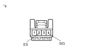
(c) Measure the voltage according to the value(s) in the table below.
Standard Voltage:
| Tester Connection | Condition | Specified Condition |
|---|---|---|
| 4 (SIG) - Body ground | Power switch on (IG) | 11 to 14 V |
(d) Measure the resistance according to the value(s) in the table below.
Standard Resistance:
| Tester Connection | Condition | Specified Condition |
|---|---|---|
| 2 (ES) - Body ground | Always | Below 1 Ω |
If the result is not as specified, repair or replace the harness or connector.
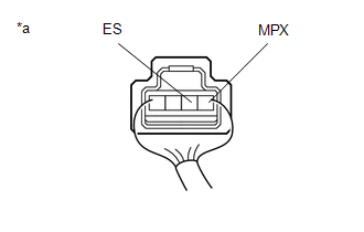
(e) Reconnect the rain sensor connector.
(f) Connect an oscilloscope to the rain sensor connector.
| (g) Check for pulses. OK
If the result is not as specified, replace the rain sensor. |
|
(h) Install the rain sensor cover.
Click here
READ NEXT:
 Removal
REMOVAL PROCEDURE 1. REMOVE RAIN SENSOR COVER (a) Detach the 2 claws and remove the rain sensor cover. 2. REMOVE RAIN SENSOR (a) Disconnect the connector. (b) Release
Inspection
INSPECTION PROCEDURE 1. INSPECT MAP LIGHT ASSEMBLY (RAIN SENSOR CIRCUIT) (a) Remove the map light assembly. Click here (b) Measure the resistance according to the value(s) in the table below. Sta
Installation
INSTALLATION PROCEDURE 1. INSTALL RAIN SENSOR TAPE NOTICE: The rain sensor tape is reusable. Only replace the tape if it is damaged or contaminated. (a) Clean the rain sensor sensing portion with a pi
SEE MORE:
Drive Motor "A" Control Module (P0A1B-505,P0A1B-806)
DTC SUMMARY MALFUNCTION DESCRIPTION These DTCs indicate that a large current flowed in the inverter for the motor. The cause of this malfunction may be one of the following: Internal inverter malfunction
Internal circuit malfunction in the inverter for the motor
Malfunction in ECU that controls
Removal
REMOVAL CAUTION / NOTICE / HINT HINT:
Use the same procedure for the RH and LH sides.
The procedure listed below is for the LH side.
PROCEDURE 1. REMOVE FRONT FENDER MOULDING SUB-ASSEMBLY LH HINT: When removing the front fender moulding sub-assembly LH, if the No. 1 moulding tape (double-sid
