- Front Corner Ultrasonic Sensor (FL Sensor)
- Front Corner Ultrasonic Sensor (FR Sensor)
- Front Center Ultrasonic Sensor (FLC Sensor)
- Front Center Ultrasonic Sensor (FRC Sensor)
- Rear Corner Ultrasonic Sensor (RL Sensor)
- Rear Corner Ultrasonic Sensor (RR Sensor)
- Rear Center Ultrasonic Sensor (RLC Sensor)
- Rear Center Ultrasonic Sensor (RRC Sensor)
Lexus NX: System Description
SYSTEM DESCRIPTION
GENERAL
(a) This system uses ultrasonic sensors to detect any obstacles at the corners and the rear of the vehicle. The system then informs the driver of the distance between the sensors and an obstacle as well as their positions by indicating them on the multi-information display (on the combination meter assembly), multi-display (on the multi-display assembly) and by sounding a buzzer.
FUNCTION OF COMPONENTS
| Component | Function |
|---|---|
| | Detects the distance between the vehicle and an obstacle |
| Sounds to inform the driver according to the distance to an obstacle |
| Multi-information Display (on Combination Meter Assembly) |
|
| Clearance Sonar Indicator (on Combination Meter Assembly) | Illuminates to inform the driver while the intuitive parking assist system power is on (the power switch is on (IG) and the intuitive parking assist system is on) |
| Combination Meter Assembly |
|
| Steering Pad Switch Assembly - Multi-information Switch | Enables, disables or cuts off the operation of the intuitive parking assist system by transmitting the switch operation signal to the combination meter assembly |
| Clearance Warning ECU Assembly |
|
| Main Body ECU (Multiplex Network Body ECU) | Transmits the destination information to the clearance warning ECU assembly |
| Hybrid Vehicle Control ECU | Transmits the shift position signal to the clearance warning ECU assembly |
| Multi-display Assembly |
|
| Parking Assist ECU*1 | Receives the ultrasonic sensor information via CAN communication and sends it to the multi-display assembly through the video signal cable |
| Rear Television Camera Assembly*2 | Receives the ultrasonic sensor information via CAN communication and sends it to the multi-display assembly through the video signal cable |
- *1: w/ Panoramic View Monitor System
- *2: w/ Parking Assist Monitor System
OPERATION EXPLANATION
(a) The operating conditions of each ultrasonic sensor differ according to the installation position as shown in the table below.
| Installation Position | Operating Condition |
|---|---|
| Front Corner |
|
| Front Center |
|
| Rear Corner |
|
| Rear Center |
When the system operates, the clearance warning ECU assembly transmits ultrasonic waves from the ultrasonic sensors. If these waves encounter an obstacle within one or more of the sensors ranges, the waves are reflected back to the sensors, which transmit them to the clearance warning ECU assembly.
Based on this information, the clearance warning ECU assembly sends signals to the combination meter assembly and the No. 1 clearance warning buzzer and No. 2 clearance warning buzzer. The approximate distance between the vehicle and the obstacle is then indicated, and the buzzer sounds.
HINT:
Refer to Detection Range Measurement and Display Inspection.
Click here .gif)
COMMUNICATION SIGNALS OF COMPONENTS
HINT:
- Allocation refers to the process of the clearance warning ECU assembly setting aside IDs for the sensors.
- The vehicle has the sensors arranged in 2 groups. There is a front series and a rear series. The sensors are connected in a "daisy chain".
(a) Initialization mode:
An ID is allocated to each sensor and sensor diagnosis is performed.
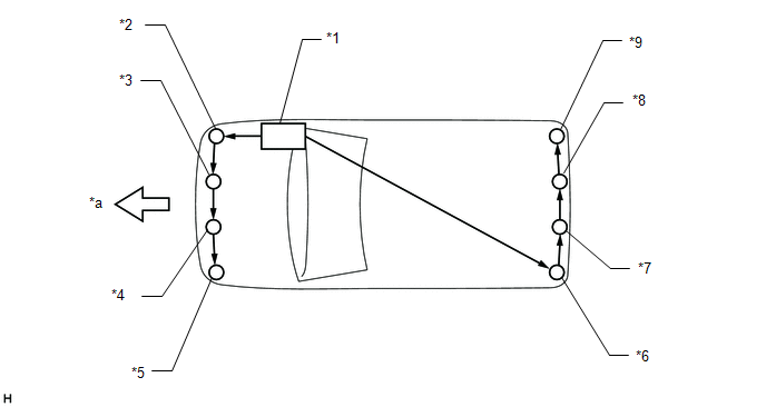
| *1 | Clearance Warning ECU Assembly | *2 | Front Corner Ultrasonic Sensor (FR Sensor) |
| *3 | Front Center Ultrasonic Sensor (FRC Sensor) | *4 | Front Center Ultrasonic Sensor (FLC Sensor) |
| *5 | Front Corner Ultrasonic Sensor (FL Sensor) | *6 | Rear Corner Ultrasonic Sensor (RL Sensor) |
| *7 | Rear Center Ultrasonic Sensor (RLC Sensor) | *8 | Rear Center Ultrasonic Sensor (RRC Sensor) |
| *9 | Rear Corner Ultrasonic Sensor (RR Sensor) | - | - |
| *a | Front | - | - |
(1) When the initial check is operating (the power switch is on (IG) and the intuitive parking assist system is on), the clearance warning ECU assembly provides power to the first sensors in each series (front left sensor and rear right sensor).
(2) After the power is supplied, the front left sensor and rear right sensor enter standby mode to receive an ID from the ECU. When a certain amount of time has elapsed, the ECU sends an ID allocation signal to these sensors.
(3) The front left sensor and rear right sensors receive the ID allocation signal from the ECU and perform self-diagnosis. When the sensor self-diagnosis is complete, the ECU sends an ID allocation confirmation signal to the sensors.
(4) After the ID allocation confirmation is performed, the ECU provides power to the second sensors in each series (front left center sensor and rear right center sensor) via the first sensors. In the same manner as the first sensors, the second sensors enter standby mode. When a certain amount of time has elapsed, the ECU sends an ID allocation signal to the second sensors.
(5) The above operation will be repeated until an ID is allocated to the last sensor (front right sensor or rear left sensor). Initialization ends when ID allocation to all ultrasonic sensors is completed.
(b) Detection mode:
After initialization mode is completed, the system switches to detection mode. In detection mode, the clearance warning ECU assembly sends information request signals and sensor activation signals to the ultrasonic sensors and receives detection result signals from the sensors.
(1) The ECU regularly sends ID signals, information request signals, and sensor activation signals to each ultrasonic sensor according to the communication schedule.
(2) When a certain amount of time has elapsed (sensor detection operation is completed), the ECU sends an ID signal to the sensor to receive a detection result signal.
(3) The ultrasonic sensor sends a detection result signal or detection information signal to the ECU.
(4) The above operation is performed repeatedly for each ultrasonic sensor.
READ NEXT:
 System Diagram
SYSTEM DIAGRAM Communication Table Sender Receiver Signal Line Main Body ECU (Multiplex Network Body ECU) Clearance Warning ECU Assembly Destination information signal CAN Commun
How To Proceed With Troubleshooting
CAUTION / NOTICE / HINT HINT:
Use the following procedure to troubleshoot the intuitive parking assist system.
*: Use the Techstream.
PROCEDURE 1. VEHICLE BROUGHT TO WORKSHOP
NE
Operation Check
OPERATION CHECK INITIAL CHECK (a) Power switch on (IG) (intuitive parking assist system off). (b) Intuitive parking assist system on and check an indication state of the vehicle mark. OK: The initial
SEE MORE:
Precaution
PRECAUTION PRECAUTIONS FOR VEHICLE PROXIMITY NOTIFICATION SYSTEM (a) In the following cases, the volume or tone of the sound might change: (1) If the vehicle is parked in a very hot or cold environment for an extended time (function will return to normal after time passes) (2) If high pressure water
Front passenger occupant classification
system
Your vehicle is equipped with a front passenger occupant classification
system.
This system detects the conditions of the front passenger seat and activates
or deactivates the front passenger airbag and seat cushion airbag in the
front passenger side.
System components
SRS warning ligh
© 2016-2026 Copyright www.lexunx.com
