Lexus NX: System Diagram
SYSTEM DIAGRAM
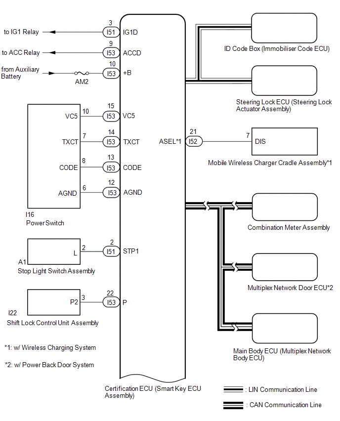
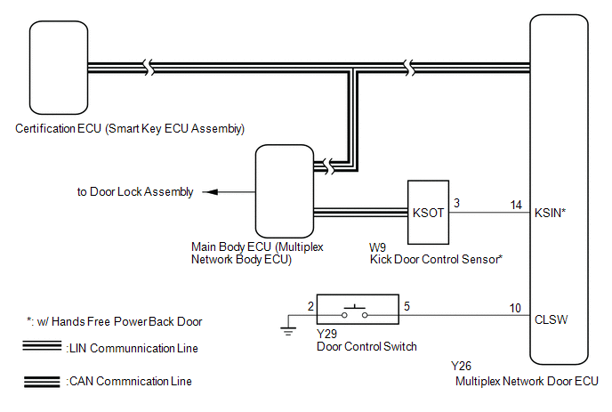
CERTIFICATION ECU (SMART KEY ECU ASSEMBLY)
| Component | Function |
|---|---|
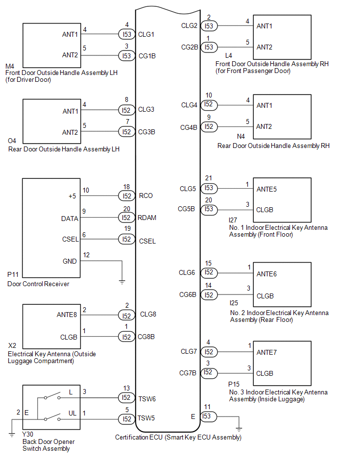
| Front door outside handle assembly | Receives request signals from the certification ECU (smart key ECU assembly) via the built-in electrical key antenna (front door) and forms the vehicle exterior detection area. Uses the built-in touch sensor (lock sensor/unlock sensor) to detect the operation of the front door outside handle assembly and sends signals to the certification ECU (smart key ECU assembly). |
| Rear door outside handle assembly | Receives request signals from the certification ECU (smart key ECU assembly) via the built-in electrical key antenna (rear door) and forms the vehicle exterior detection area. Uses the built-in touch sensor (lock sensor/unlock sensor) to detect the operation of the rear door outside handle assembly and sends signals to the certification ECU (smart key ECU assembly). |
| No. 1 indoor electrical key antenna assembly (front floor) No. 2 indoor electrical key antenna assembly (rear floor) No. 3 indoor electrical key antenna assembly (inside luggage) | Receives the request code from the certification ECU (smart key ECU assembly) and forms the vehicle interior detection area. |
| Electrical key antenna (outside luggage compartment) | Receives the request code from the certification ECU (smart key ECU assembly) and forms the back door exterior detection area. |
| Back door opener switch assembly | Sends switch operation signals to the certification ECU (smart key ECU assembly). |
| Door control receiver | Receives the smart access system with push-button start code/wireless code sent from the electrical key transmitter sub-assembly and sends it to the certification ECU (smart key ECU assembly). |
| Wireless door lock buzzer | Sounds when warning functions operate in accordance with certification ECU (smart key ECU assembly) control. |
| Electrical key transmitter sub-assembly | Sends the ID code upon receiving a request signal. |
| Certification ECU (smart key ECU assembly) | Sends request codes to each electrical key antenna. Distinguishes and verifies the ID code from the electrical key transmitter sub-assembly and sends signals to each ECU in response to operated functions (controls entire system). Performs encryption code communication with the ID code box (immobiliser code ECU) when ignition operations are performed. |
Wireless Door Lock Control System
.png)
.png)
.png)
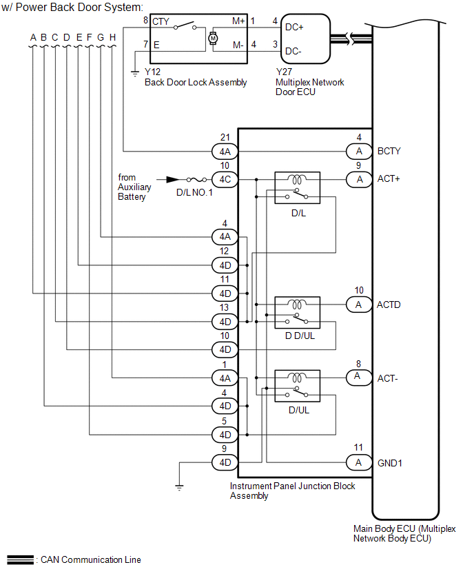
Power Back Door System (w/ Power Back Door System)
READ NEXT:
 System Description
SYSTEM DESCRIPTION MULTI CHANNEL FUNCTION (a) The electrical key transmitter sub-assembly and door control receiver can operate on two different RF channels. When an electrical key transmitter sub-ass
How To Proceed With Troubleshooting
CAUTION / NOTICE / HINT HINT:
Use these procedures to troubleshoot the smart access system with push-button start (for Entry Function).
*: Use the Techstream.
PROCEDURE 1. VEHICLE BROUGH
Customize Parameters
CUSTOMIZE PARAMETERS CUSTOMIZE SMART ACCESS SYSTEM WITH PUSH-BUTTON START (for Entry Function) HINT: The following items can be customized. NOTICE:
When the customer requests a change in a function
SEE MORE:
Remote Touch Screen Does not Generate Vibration Feedback
DESCRIPTION When each button displayed on the multi-display assembly is selected via remote touch screen operation, the remote touch screen generates vibration feedback according to communication between the remote touch and radio receiver assembly. CAUTION / NOTICE / HINT NOTICE: When replacing the
Removal
REMOVAL PROCEDURE 1. REMOVE BACK DOOR CENTER GARNISH Click here 2. REMOVE BACK DOOR SIDE GARNISH LH Click here 3. REMOVE BACK DOOR SIDE GARNISH RH Click here 4. REMOVE BACK DOOR TRIM BASE (w/ Power Back Door) Click here 5. REMOVE PULL HANDLE (w/ Power Back Door) Click here 6. REMOVE B
