Lexus NX: Components
COMPONENTS
ILLUSTRATION
.png)
| *1 | DECK FLOOR BOX LH | *2 | NO. 3 DECK BOARD SUB-ASSEMBLY |
| *3 | REAR DECK FLOOR BOX | *4 | NEGATIVE AUXILIARY BATTERY TERMINAL |
.png) | N*m (kgf*cm, ft.*lbf): Specified torque | - | - |
ILLUSTRATION
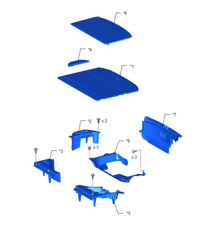
| *1 | DECK BOARD ASSEMBLY | *2 | DECK FLOOR BOX RH |
| *3 | NO. 1 TOOL BOX SUB-ASSEMBLY | *4 | NO. 2 DECK BOARD SUB-ASSEMBLY |
| *5 | NO. 2 TOOL BOX SUB-ASSEMBLY | *6 | REAR FLOOR CARPET |
| *7 | REAR FLOOR FINISH PLATE | *8 | TONNEAU COVER ASSEMBLY |
ILLUSTRATION
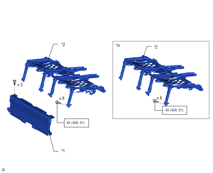
| *A | for Power Seat | - | - |
| *1 | BATTERY SERVICE COVER BOARD | *2 | NO. 1 SEAT LEG ASSEMBLY |
| | N*m (kgf*cm, ft.*lbf): Specified torque | - | - |
ILLUSTRATION
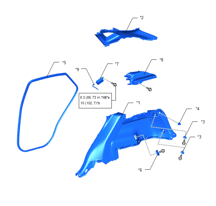
| *1 | DECK TRIM SIDE PANEL ASSEMBLY RH | *2 | INNER ROOF SIDE GARNISH ASSEMBLY RH |
| *3 | LUGGAGE HOLD BELT STRIKER ASSEMBLY | *4 | NO. 1 LUGGAGE COMPARTMENT TRIM HOOK |
| *5 | REAR DOOR OPENING TRIM WEATHERSTRIP RH | *6 | ROPE HOOK ASSEMBLY |
| *7 | TIRE PRESSURE WARNING ECU AND RECEIVER | *8 | UPPER DECK TRIM SIDE BOARD RH |
| *9 | CONNECTOR | - | - |
| *a | for bolt A | *b | for bolt B |
| | N*m (kgf*cm, ft.*lbf): Specified torque | - | - |
READ NEXT:
 Removal
REMOVAL PROCEDURE 1. PRECAUTION NOTICE: After turning the power switch off, there may be a waiting time before disconnecting the negative (-) auxiliary battery terminal. Click here 2. REMOVE DECK BO
Installation
INSTALLATION PROCEDURE 1. INSTALL TIRE PRESSURE WARNING ECU AND RECEIVER (a) Connect the connector to the tire pressure warning ECU and receiver. (b) Attach the 2 guides to temporarily install the tir
SEE MORE:
Seat Heater for Front Left Seat does not Operate
DESCRIPTION When the seat heater switch on air conditioning control assembly is operated, the air conditioning amplifier assembly receives the signal. The air conditioning amplifier assembly receives the signal and operates the front seat heater. WIRING DIAGRAM CAUTION / NOTICE / HINT NOTICE:
If
BSM (Blind Spot Monitor)
The Blind Spot Monitor uses the
sensors installed behind the rear
bumper. The system is intended to
assist the driver check areas that
are not easily visible. The system
has the following 2 functions:
The Blind Spot Monitor function
Assists the driver in making the decision
when changin
