Lexus NX: Terminals Of Ecu
TERMINALS OF ECU
CHECK FORWARD RECOGNITION CAMERA
NOTICE:
DTCs may be output when connectors are disconnected during inspection. Therefore, be sure to clear the DTCs using the Techstream once the inspection has been completed.

(a) Measure the voltage and resistance according to the value(s) in the table below.
| Terminal No. (Symbol) | Wiring Color | Terminal Description | Condition | Specified Condition |
|---|---|---|---|---|
| T18-7 (IGB) - T17-10 (GND) | GR - W-B | Power source | Power switch on (IG) | 11 to 14 V |
| Power switch off | Below 1 V | |||
| T18-3 (LKSW) - T18-10 (GND) | P - W-B | Steering pad switch signal | Power switch off, LTA/LDA main switch off | 1 MΩ or higher |
| Power switch off, LTA/LDA main switch on | 228 to 252 Ω | |||
| T18-10 (GND) - Body ground | W-B - Body ground | Ground | Always | Below 1 Ω |
(b) Check for pulses according to the value(s) in the table below.
| Terminal No. (Symbol) | Wiring Color | Terminal Description | Condition | Specified Condition |
|---|---|---|---|---|
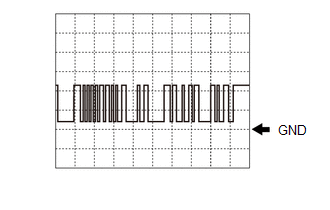
| T18-2 (STRV) - Body ground | B - Body ground | CAN communication signal | Power switch on (IG) | Pulse generation (See waveform 1) |
(1) WAVEFORM 1
| Item | Content |
|---|---|
| Terminal Name | Between T18-2 (STRV) and Body ground |
| Tester Range | 5 V/DIV., 1 ms/DIV. |
| Condition | Power switch ON |
HINT:
The waveform varies depending on the CAN communication signal.
READ NEXT:
 Diagnosis System
DIAGNOSIS SYSTEM DIAGNOSIS MODE FUNCTION (a) w/ Lane Centering Function: When a malfunction occurs in the lane tracing assist system system, the LTA indicator light illuminates yellow and a message is
Dtc Check / Clear
DTC CHECK / CLEAR CHECK DTC (a) Connect the Techstream to the DLC3. (b) Turn the power switch on (IG). (c) Turn the Techstream on. (d) Enter the following menus: Chassis / Lane Control / Trouble Codes
Freeze Frame Data
FREEZE FRAME DATA DESCRIPTION (a) Whenever a lane tracing assist system DTC is stored, the forward recognition camera stores the current vehicle state (ECU and sensor information) as Freeze Frame Data
SEE MORE:
Drive Motor "B" Temperature Sensor Circuit Range / Performance (P0A31-668,P0A34-667)
DESCRIPTION The resistance of the thermistor built into the rear motor temperature sensor changes in accordance with changes in the rear motor temperature. The lower the rear motor temperature, the higher the thermistor resistance. Conversely, the higher the rear motor temperature, the lower the res
Components
COMPONENTS ILLUSTRATION *A for 8 Speakers *B for 10 Speakers *C for 14 Speakers - - *1 FRONT DOOR INSIDE HANDLE BEZEL PLUG LH *2 FRONT DOOR TRIM BOARD SUB-ASSEMBLY LH *3 FRONT DOOR TRIM COVER LH *4 FRONT NO. 1 SPEAKER ASSEMBLY *5 POWER WINDOW REGULATOR M
