Lexus NX: Drive Motor "B" Temperature Sensor Circuit Range / Performance (P0A31-668,P0A34-667)
DESCRIPTION
The resistance of the thermistor built into the rear motor temperature sensor changes in accordance with changes in the rear motor temperature. The lower the rear motor temperature, the higher the thermistor resistance. Conversely, the higher the rear motor temperature, the lower the resistance.
HINT:
The term "drive motor B" indicates the rear motor (MGR)
| DTC No. | Detection Item | DTC Detection Condition | Trouble Area | MIL | Warning Indicate |
|---|---|---|---|---|---|
| P0A31-668 | Drive Motor "B" Temperature Sensor Circuit Range / Performance | Rear motor temperature sensor output does not increase under conditions in which the value should increase. (1 trip detection logic) |
| Does not come on | Master Warning Light: Comes on |
| P0A34-667 | Drive Motor "B" Temperature Sensor Circuit Intermittent | Unusual sudden change in rear motor temperature sensor output occurs and the condition continues, or unusual sudden change in motor temperature sensor output occurs repeatedly. (1 trip detection logic) |
| Does not come on | Master Warning Light: Comes on |
| DTC No. | Data List |
|---|---|
| P0A31-668 | Rear Motor Temp |
| P0A34-667 |
CAUTION / NOTICE / HINT
HINT:
-
If DTC P0A31-668 is output, clear the DTCs, perform the following procedure, and check that the same DTC is not output after the repair.
- Drive the vehicle (stop and go driving) on urban roads for approximately 5 minutes. If the Data List item "Rear Motor Temp" shows both increases and decreases in temperature, suspected areas indicated by this DTC are not malfunctioning.
-
If DTC P0A34-667 is output, clear the DTCs, perform the following procedure, and check that the same DTC is not output after the repair.
- Turn the power switch on (READY) and wait for 30 seconds or more.
- Drive the vehicle for approximately 5 minutes according to the freeze frame data items "Vehicle Spd", "Rear Motor Temp".
PROCEDURE
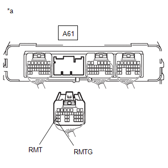
| 1. | CHECK CONNECTOR CONNECTION CONDITION (HYBRID VEHICLE CONTROL ECU CONNECTOR) |
Click here .gif)
| Result | Proceed to |
|---|---|
| OK | A |
| NG (The connector is not connected securely.) | B |
| NG (The terminals are not making secure contact or are deformed, or water or foreign matter exists in the connector.) | C |
| B | .gif) | CONNECT SECURELY |
| C | | REPAIR OR REPLACE HARNESS OR CONNECTOR |
|
.gif)
| 2. | CHECK HARNESS AND CONNECTOR (NO. 2 FLOOR WIRE - HYBRID VEHICLE CONTROL ECU) |
(a) Disconnect the A61 hybrid vehicle control ECU connector.
| (b) Measure the resistance according to the value(s) in the table below. Standard Resistance:
|
|
(c) Reconnect the A61 hybrid vehicle control ECU connector.
| NG | | GO TO STEP 9 |
|
| 3. | CHECK CONNECTOR CONNECTION CONDITION (NO. 2 FLOOR WIRE CONNECTOR) |
Click here
| Result | Proceed to |
|---|---|
| OK | A |
| NG (The connector is not connected securely.) | B |
| NG (The terminals are not making secure contact or are deformed, or water or foreign matter exists in the connector.) | C |
| B | | CONNECT SECURELY |
| C | | REPAIR OR REPLACE HARNESS OR CONNECTOR |
|
| 4. | CHECK HARNESS AND CONNECTOR (HYBRID VEHICLE CONTROL ECU - NO. 2 FLOOR WIRE) |
(a) Disconnect the AQ3 No. 2 floor wire connector.
(b) Disconnect the A61 hybrid vehicle control ECU connector.
(c) Measure the resistance according to the value(s) in the table below.
HINT:
When performing the measurement, lightly jiggle the wire harness up and down and left and right and confirm that the resistance does not fluctuate.
Standard Resistance (Check for Open):
| Tester Connection | Condition | Specified Condition |
|---|---|---|
| AQ3-13 (RMT) - A61-27 (RMT) | Power switch off | Below 1 Ω |
| AQ3-14 (RMTG) - A61-35 (RMTG) | Power switch off | Below 1 Ω |
Standard Resistance (Check for Short):
| Tester Connection | Condition | Specified Condition |
|---|---|---|
| AQ3-13 (RMT) or A61-27 (RMT) - Body ground and other terminals | Power switch off | 10 kΩ or higher |
| AQ3-14 (RMTG) or A61-35 (RMTG) - Body ground and other terminals | Power switch off | 10 kΩ or higher |
(d) Reconnect the A61 hybrid vehicle control ECU connector.
(e) Reconnect the AQ3 No. 2 floor wire connector.
| NG | | REPAIR OR REPLACE HARNESS OR CONNECTOR |
|
| 5. | CHECK CONNECTOR CONNECTION CONDITION (NO. 4 FLOOR WIRE CONNECTOR) |
Click here
| Result | Proceed to |
|---|---|
| OK | A |
| NG (The connector is not connected securely.) | B |
| NG (The terminals are not making secure contact or are deformed, or water or foreign matter exists in the connector.) | C |
| B | | CONNECT SECURELY |
| C | | REPAIR OR REPLACE HARNESS OR CONNECTOR |
|
| 6. | CHECK HARNESS AND CONNECTOR (NO. 4 FLOOR WIRE - NO. 2 FLOOR WIRE) |
(a) Disconnect the RQ2 No. 4 floor wire connector.
(b) Disconnect the AQ3 No. 2 floor wire connector.
(c) Measure the resistance according to the value(s) in the table below.
HINT:
When performing the measurement, lightly jiggle the wire harness up and down and left and right and confirm that the resistance does not fluctuate.
Standard Resistance (Check for Open):
| Tester Connection | Condition | Specified Condition |
|---|---|---|
| AQ3-13 (RMT) - RQ2-6 (RMT) | Power switch off | Below 1 Ω |
| AQ3-14 (RMTG) - RQ2-7 (RMTG) | Power switch off | Below 1 Ω |
Standard Resistance (Check for Short):
| Tester Connection | Condition | Specified Condition |
|---|---|---|
| AQ3-13 (RMT) or RQ2-6 (RMT) - Body ground and other terminals | Power switch off | 10 kΩ or higher |
| AQ3-14 (RMTG) or RQ2-7 (RMTG) - Body ground and other terminals | Power switch off | 10 kΩ or higher |
(d) Reconnect the RQ2 No. 4 floor wire connector.
(e) Reconnect the AQ3 No. 2 floor wire connector.
| NG | | REPAIR OR REPLACE HARNESS OR CONNECTOR |
|
| 7. | CHECK CONNECTOR CONNECTION CONDITION (REAR MOTOR TEMPERATURE SENSOR CONNECTOR) |
Click here
| Result | Proceed to |
|---|---|
| OK | A |
| NG (The connector is not connected securely.) | B |
| NG (The terminals are not making secure contact or are deformed, or water or foreign matter exists in the connector.) | C |
| B | | CONNECT SECURELY |
| C | | REPAIR OR REPLACE HARNESS OR CONNECTOR |
|
| 8. | CHECK HARNESS AND CONNECTOR (REAR MOTOR TEMPERATURE SENSOR - NO. 4 FLOOR WIRE) |
(a) Disconnect the RQ2 No. 4 floor wire connector.
(b) Remove the rear suspension member sub-assembly.
Click here
(c) Disconnect the R2 rear motor temperature sensor connector.
(d) Measure the resistance according to the value(s) in the table below.
Standard Resistance (Check for Open):
| Tester Connection | Condition | Specified Condition |
|---|---|---|
| RQ2-6 (RMT) - R2-1 (RMT) | Power switch off | Below 1 Ω |
| RQ2-7 (RMTG) - R2-3 (RMTG) | Power switch off | Below 1 Ω |
Standard Resistance (Check for Short):
| Tester Connection | Condition | Specified Condition |
|---|---|---|
| RQ2-6 (RMT) or R2-1 (RMT) - Body ground and other terminals | Power switch off | 10 kΩ or higher |
| RQ2-7 (RMTG) or R2-3 (RMTG) - Body ground and other terminals | Power switch off | 10 kΩ or higher |
(e) Reconnect the R2 rear motor temperature sensor connector.
(f) Reinstall the rear suspension member sub-assembly.
(g) Reconnect the RQ2 No. 4 floor wire connector.
| OK | | REPLACE REAR TRACTION MOTOR WITH TRANSAXLE ASSEMBLY |
| NG | | REPAIR OR REPLACE HARNESS OR CONNECTOR |
| 9. | INSPECT REAR TRACTION MOTOR WITH TRANSAXLE ASSEMBLY (REAR MOTOR TEMPERATURE SENSOR) |
(a) Disconnect the AQ3 No. 2 floor wire connector.
(b) Measure the resistance according to the value(s) in the table below.
Standard Resistance:
| Tester Connection | Condition | Specified Condition |
|---|---|---|
| AQ3-13 (RMT) - AQ3-14 (RMTG) | Power switch off | 0.3443 to 1446 kΩ |
(c) Reconnect the AQ3 No. 2 floor wire connector.
| OK | | REPAIR OR REPLACE HARNESS OR CONNECTOR (NO. 2 FLOOR WIRE - HYBRID VEHICLE CONTROL ECU) |
|
| 10. | INSPECT REAR TRACTION MOTOR WITH TRANSAXLE ASSEMBLY (REAR MOTOR TEMPERATURE SENSOR) |
(a) Disconnect the RQ2 No. 4 floor wire connector.
(b) Measure the resistance according to the value(s) in the table below.
Standard Resistance:
| Tester Connection | Condition | Specified Condition |
|---|---|---|
| RQ2-6 (RMT) - RQ2-7 (RMTG) | Power switch off | 0.3443 to 1446 kΩ |
(c) Reconnect the RQ2 No. 4 floor wire connector.
| OK | | REPAIR OR REPLACE HARNESS OR CONNECTOR (NO. 4 FLOOR WIRE - NO. 2 FLOOR WIRE) |
|
| 11. | INSPECT REAR TRACTION MOTOR WITH TRANSAXLE ASSEMBLY (REAR MOTOR TEMPERATURE SENSOR) |
Click here
| OK | | REPAIR OR REPLACE HARNESS OR CONNECTOR (REAR MOTOR TEMPERATURE SENSOR - NO. 4 FLOOR WIRE) |
| NG | | REPLACE REAR TRACTION MOTOR WITH TRANSAXLE ASSEMBLY |
READ NEXT:
 Drive Motor "B" Temperature Sensor Circuit Low (P0A32-666,P0A33-665)
DESCRIPTION Refer to the description for DTC P0A31-668. Click here HINT: The term "drive motor B" indicates the rear motor (MGR). DTC No. Detection Item DTC Detection Condition Trouble Area
Generator Temperature Sensor Circuit Range / Performance (P0A37-260,P0A3A-258)
DESCRIPTION The resistance of the thermistor built into the generator temperature sensor changes in accordance with changes in generator (MG1) temperature. The lower the generator (MG1) temperature, t
Generator Temperature Sensor Circuit Low (P0A38-257,P0A39-259)
DESCRIPTION Refer to the description for DTC P0A37-260. Click here DTC No. Detection Item DTC Detection Condition Trouble Area MIL Warning Indicate P0A38-257 Generator Temperature
SEE MORE:
Components
COMPONENTS ILLUSTRATION *1 FOG LIGHT ASSEMBLY LH *2 FRONT BUMPER ASSEMBLY
Parts Location
PARTS LOCATION ILLUSTRATION *1 IGNITION COIL ASSEMBLY *2 ECM *3 NO. 1 ENGINE ROOM RELAY BLOCK LH - IGN FUSE *4 SPARK PLUG
