Lexus NX: Terminals Of Ecu
TERMINALS OF ECU
CHECK SLIDING ROOF ECU (SLIDING ROOF DRIVE GEAR SUB-ASSEMBLY)
(a) Disconnect the T9 sliding roof ECU (sliding roof drive gear sub-assembly) connector.
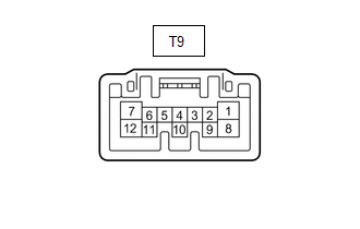
(b) Measure the resistance and voltage according to the value(s) in the table below.
| Tester Connection | Wiring Color | Terminal Description | Condition | Specified Condition |
|---|---|---|---|---|
| T9-1 (IG) - Body ground | L - Body ground | IG power supply | Power switch off | Below 1 V |
| Power switch on (IG) | 11 to 14 V | |||
| T9-4 (UP) - Body ground | W - Body ground | Slide roof switch (UP) signal | Slide roof switch (UP) off → on | 1 kΩ or higher → Below 100 Ω |
| T9-5 (CLS) - Body ground | B - Body ground | Slide roof switch (CLOSE) signal | Slide roof switch (CLOSE) off → on | 1 kΩ or higher → Below 100 Ω |
| T9-6 (DWN) - Body ground | L - Body ground | Slide roof switch (DOWN) signal | Slide roof switch (DOWN) off → on | 1 kΩ or higher → Below 100 Ω |
| T9-7 (OPN) - Body ground | R - Body ground | Slide roof switch (OPEN) signal | Slide roof switch (OPEN) off → on | 1 kΩ or higher → Below 100 Ω |
| T9-8 (B) - Body ground | W - Body ground | Battery power supply | Power switch off | 11 to 14 V |
| T9-12 (E) - Body ground | W-B - Body ground | Ground | Always | Below 1 Ω |
CHECK MAIN BODY ECU (MULTIPLEX NETWORK BODY ECU)
Click here .gif)
READ NEXT:
 Diagnosis System
DIAGNOSIS SYSTEM DESCRIPTION (a) Sliding roof system data and Diagnostic Trouble Codes (DTCs) can be read through the vehicle Data Link Connector 3 (DLC3). When the system seems to be malfunctioning,
Dtc Check / Clear
DTC CHECK / CLEAR CHECK DTC (a) Connect the Techstream to the DLC3. (b) Turn the power switch on (IG). (c) Turn the Techstream on. (d) Enter the following menus: Body Electrical / Sliding Roof / Troub
Data List / Active Test
DATA LIST / ACTIVE TEST DATA LIST HINT: Using the Techstream to read the Data List allows the values or states of switches, sensors, actuators and other items to be read without removing any parts. Th
SEE MORE:
Components
COMPONENTS ILLUSTRATION *1 NO. 1 AIR DUCT *2 QUICK HEATER ASSEMBLY ● Non-reusable part - -
Start Up Signal Circuit between Radio Receiver Assembly and Navigation ECU
DESCRIPTION This circuit includes the navigation ECU and radio and display receiver assembly. WIRING DIAGRAM PROCEDURE 1. CHECK HARNESS AND CONNECTOR (RADIO RECEIVER ASSEMBLY - NAVIGATION ECU) (a) Disconnect the I153 radio receiver assembly connector. (b) Disconnect the I173 navigation ECU
