Lexus NX: Terminals Of Ecu
TERMINALS OF ECU
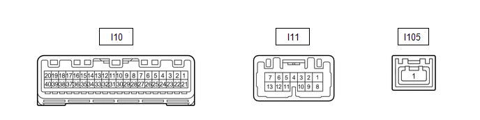
CHECK COMBINATION METER ASSEMBLY
(a) Disconnect the I10 combination meter assembly connector.
(b) Measure the resistance and voltage according to the value(s) in the table below.
| Tester Connection | Wiring Color | Terminal Description | Condition | Specified Condition |
|---|---|---|---|---|
| I10-21 (IG+) - Body ground | B - Body ground | IG power supply | Power switch on (IG) → off | 11 to 14 V → Below 1 V |
| I10-22 (B) - Body ground | Y - Body ground | Battery power supply | Always | 11 to 14 V |
| I10-31 (ES) - Body ground | W-B - Body ground | Ground | Always | Below 1 Ω |
(c) Reconnect the I10 combination meter assembly connector.
(d) Measure the voltage according to the value(s) in the table below.
| Tester Connection | Wiring Color | Terminal Description | Condition | Specified Condition |
|---|---|---|---|---|
| I10-6 (P/SB) - Body ground | L - Body ground | Front passenger seat belt buckle switch signal | Power switch on (IG), front passenger seat occupied, seat belt unfastened → fastened | 11 to 14 V → Below 1 V |
| I10-12 (RRSB) - Body ground | W - Body ground | Rear RH seat belt buckle switch signal | Rear RH seat belt unfastened → fastened | 11 to 14 V → Below 1 V |
| I10-13 (RCSB) - Body ground | B - Body ground | Rear center seat belt buckle switch signal | Rear center seat belt unfastened → fastened | 11 to 14 V → Below 1 V |
| I10-14 (RLSB) - Body ground | G - Body ground | Rear LH seat belt buckle switch signal | Rear LH seat belt unfastened → fastened | 11 to 14 V → Below 1 V |
| I10-35 (RLMT) - Body ground | W - Body ground | Rear LH seat belt warning light signal | Rear LH seat belt unfastened → fastened | 11 to 14 V → Below 1 V |
| I10-36 (RCMT) - Body ground | G - Body ground | Rear center seat belt fastened | Rear center seat belt unfastened → fastened | 11 to 14 V → Below 1 V |
| I10-37 (RRMT) - Body ground | L - Body ground | Rear RH seat belt warning light signal | Rear RH seat belt unfastened → fastened | 11 to 14 V → Below 1 V |
CHECK AIRBAG ECU ASSEMBLY
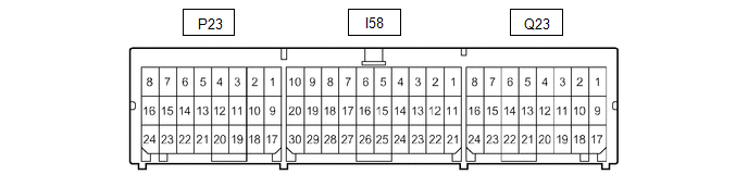
| Terminal No. | Terminal Symbol | Destination |
|---|---|---|
| Q23-15 | LBE+ | Front seat inner belt assembly LH |
| Q23-23 | LBE- | Front seat inner belt assembly LH |
| P23-9 | FSR+ | Occupant detection ECU |
| P23-17 | FSR- | Occupant detection ECU |
CHECK OCCUPANT DETECTION ECU

HINT:
Since the occupant detection ECU uses waterproof connectors, the voltage and waveform cannot be inspected directly. Standard voltage readings and waveforms are indicated for reference only.
| Terminal No. (Symbol) | Wiring Color | Terminal Description | Condition | Specified Condition |
|---|---|---|---|---|
| f14-1 (SVC1) - f14-5 (SGD1) | R - G | Front occupant classification sensor LH power supply | Power switch on (IG) | 4.9 to 5.1 V |
| f14-2 (SVC3) - f14-6 (SGD3) | GR - W | Rear occupant classification sensor LH power supply | Power switch on (IG) | 4.9 to 5.1 V |
| f14-3 (SIG1) - f14-5 (SGD1) | P - G | Front occupant classification sensor LH signal | Power switch on (IG) | Pulse generation |
| f14-4 (SIG3) - f14-6 (SGD3) | SB - W | Rear occupant classification sensor LH signal | Power switch on (IG) | Pulse generation |
| f14-5 (SGD1) - f15-3 (GND) | G - W-B | Front occupant classification sensor LH ground | Always | Below 1 V |
| f14-6 (SGD3) - f15-3 (GND) | W - W-B | Rear occupant classification sensor LH ground | Always | Below 1 V |
| f15-1 (+B) - f15-3 (GND) | W - W-B | Power source (+B) | Power switch off | 11 to 14 V |
| f15-2 (DIA) | GR | Diagnosis (DLC3) | -* | -* |
| f15-3 (GND) - Body ground | W-B - Body ground | Ground | Always | Below 1 V |
| f15-4 (FSR-) - f15-3 (GND) | LG - W-B | Airbag ECU assembly communication signal | Always | Below 1 V |
| f15-5 (BGND) - f15-3 (GND) | P - W-B | Front Passenger side buckle switch ground | Always | Below 1 V |
| f15-6 (IG2) - f15-3 (GND) | B - W-B | Power source (IG) | Power switch on (IG) | 11 to 14 V |
| f15-7 (FSR+) - f15-4 (FSR-) | L - LG | Airbag ECU assembly communication signal | Power switch on (IG) | Pulse generation |
| f15-8 (BSW) - f15-5 (BGND) | G - P | Front Passenger side buckle switch signal | Always | Pulse generation |
- *: As this is a line that is connected to other systems, voltage changes according to the systems that are connected.
READ NEXT:
 Diagnosis System
DIAGNOSIS SYSTEM CHECK DLC3 (a) Check the DLC3. Click here INSPECT AUXILIARY BATTERY VOLTAGE (a) Measure the auxiliary battery voltage. Standard voltage: 11 to 14 V (power switch off) If the vo
Data List / Active Test
DATA LIST / ACTIVE TEST DATA LIST NOTICE: In the following table, the values listed under "Normal Condition" are reference values. Do not depend solely on these reference values when deciding whether
Driver Side Seat Belt Warning Light does not Operate
DESCRIPTION The combination meter assembly illuminates, blinks or turns off the front seat belt warning light on the combination meter assembly in accordance with the state of the front seat inner bel
SEE MORE:
Installation
INSTALLATION CAUTION / NOTICE / HINT HINT: A bolt without a torque specification is shown in the standard bolt chart. Click here PROCEDURE 1. INSTALL REAR NO. 2 SIDE RAIL SPACER LH (a) Attach the 2 claws to install the rear No. 2 side rail spacer LH. (b) Install the 2 bolts. 2. INSTALL REAR NO. 2
Removal
REMOVAL CAUTION / NOTICE / HINT HINT:
Use the same procedure for the RH and LH sides.
The procedure listed below is for the LH side.
PROCEDURE 1. REMOVE REAR WHEEL Click here 2. REMOVE REAR SUSPENSION ARM COVER LH (a) Remove the 2 bolts and disengage the 2 claws to remove the rear suspe
