- BCC Malfunction
- Abnormal Status
- Different Encrypt Code
- Different Serial Number
- Frame Error
-
Response
HINT:
If immobiliser key code verification communication is not performed correctly, the malfunction may be indicated by one or more of the Data List items listed above
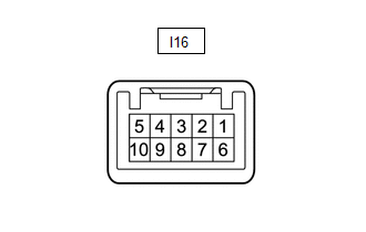
Lexus NX: Terminals Of Ecu
Lexus NX Service Manual / Vehicle Interior / Theft Deterrent / Keyless Entry / Immobiliser System / Terminals Of Ecu
TERMINALS OF ECU
CHECK POWER SWITCH
(a) Measure the voltage and resistance according to the value(s) in the table below.
| Terminal No. (Symbol) | Input/Output | Wiring Color | Terminal Description | Condition | Specified Condition | Related Data List Item/DTC |
|---|---|---|---|---|---|---|
| I16-6 (AGND) - Body ground | - | P - Body ground | Transponder key amplifier ground | Always | Below 1 Ω | - |
| I16-7 (TXCT) - I16-6 (AGND) | Input | L - P | Immobiliser communication input | Power switch off, brake pedal not depressed, 30 seconds or more elapsed after driver door opened and then closed | Below 1 V | - |
| I16-8 (CODE) - I16-6 (AGND) | Output | W - P | Immobiliser communication output | Power switch off, brake pedal not depressed, 30 seconds or more elapsed after driver door opened and then closed | Below 1 V | - |
| I16-10 (VC5) - I16-6 (AGND) | Input | R - P | Transponder key amplifier power supply | Power switch off, brake pedal not depressed, 30 seconds or more elapsed after driver door opened and then closed | Below 1 V | - |
(b) Check for pulses according to the value(s) in the table below.
| Terminal No. (Symbol) | Input/Output | Wiring Color | Terminal Description | Condition | Specified Condition | Related Data List Item/DTC |
|---|---|---|---|---|---|---|
| I16-7 (TXCT) - I16-6 (AGND) | Input | L - P | Signal input from certification ECU (smart key ECU assembly) (Code sent from certification ECU (smart key ECU assembly) to transponder key amplifier built into power switch, and then transmitted by transponder key amplifier antenna as radio waves) | Power switch off, key not in cabin, within 30 seconds after power switch pressed | Pulse generation (See waveform 1) | |
| I16-8 (CODE) - I16-6 (AGND) | Output | W - P | Signal output to certification ECU (smart key ECU assembly) (Radio waves from transponder key amplifier built into power switch used to detect key information. Key information then sent to certification ECU (smart key ECU assembly)) | Power switch off, power switch pressed with key held near power switch* | Pulse generation (See waveform 2) | |
| I16-10 (VC5) - I16-6 (AGND) | Input | R - P | Transponder key amplifier power supply (Power supplied from certification ECU (smart key ECU assembly) when transponder key amplifier built into power switch activated) | Power switch off, key not in cabin, within 30 seconds after power switch pressed | Pulse generation (See waveform 3) |
HINT:
*: Remove the transmitter battery before performing this inspection.
(c) Using an oscilloscope, check the waveform.
NOTICE:
The waveform shown in the illustration is an example for reference only. Noise, chattering, etc. are not shown.
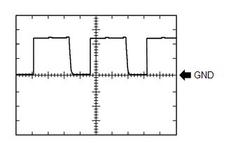
(1) Waveform 1 (Reference)
 Measurement Condition
 | Item | Content |
|---|---|
| Tester Connection | I16-7 (TXCT) - I16-6 (AGND) |
| Tool Setting | 2 V/DIV., 20 ms./DIV. |
| Condition | Power switch off, key not in cabin, within 30 seconds after power switch pressed |
(2) Waveform 2 (Reference)
 Measurement Condition
 | Item | Content |
|---|---|
| Tester Connection | I16-8 (CODE) - I16-6 (AGND) |
| Tool Setting | 2 V/DIV., 20 ms./DIV. |
| Condition | Power switch off, power switch pressed with key held near power switch* |
HINT:
*: Remove the transmitter battery before performing this inspection.
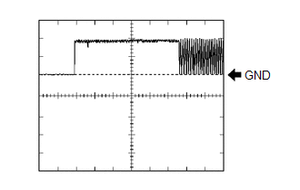
(3) Waveform 3 (Reference)
 Measurement Condition
 | Item | Content |
|---|---|
| Tester Connection | I16-10 (VC5) - I16-6 (AGND) |
| Tool Setting | 2 V/DIV., 200 ms./DIV. |
| Condition | Power switch off, key not in cabin, within 30 seconds after power switch pressed |
CHECK CERTIFICATION ECU (SMART KEY ECU ASSEMBLY)
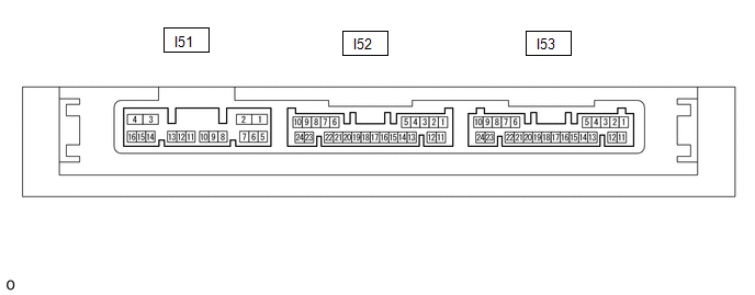
(a) Disconnect the I53 certification ECU (smart key ECU assembly) connector.
(b) Measure the voltage and resistance according to the value(s) in the table below.
| Terminal No. (Symbol) | Input/Output | Wiring Color | Terminal Description | Condition | Specified Condition | Related Data List Item/DTC |
|---|---|---|---|---|---|---|
| I53-10 (+B) - I53-11 (E) | Input | W - W-B | +B power supply | Power switch off | 11 to 14 V | - |
| I53-11 (E) - Body ground | - | W-B - Body ground | Ground | Always | Below 1 Ω | - |
(c) Reconnect the I53 certification ECU (smart key ECU assembly) connector.
(d) Measure the voltage and resistance and check for pulses according to the value(s) in the table below.
| Terminal No. (Symbol) | Input/Output | Wiring Color | Terminal Description | Condition | Specified Condition | Related Data List Item/DTC |
|---|---|---|---|---|---|---|
| I53-14 (TXCT) - I53-12 (AGND) | Output | L - P | Signal output to transponder key amplifier | Power switch off, brake pedal not depressed, 30 seconds or more elapsed after driver door opened and then closed | Below 1 V |
|
| I53-13 (CODE) - I53-12 (AGND) | Input | W - P | Signal input from transponder key amplifier | Power switch off, brake pedal not depressed, 30 seconds or more elapsed after driver door opened and then closed | Below 1 V | |
| I53-15 (VC5) - I53-12 (AGND) | Output | R - P | Transponder key amplifier power supply | Power switch off, brake pedal not depressed, 30 seconds or more elapsed after driver door opened and then closed | Below 1 V | |
| I53-12 (AGND) - Body ground | - | P - Body ground | Transponder key amplifier ground | Always | Below 1 Ω | |
| I53-19 (IND) - I53-11 (E) | Output | P - W-B | Security indicator output | Power switch off → on (IG) | Pulse generation → Below 2 V | - |
(e) Check for pulses according to the value(s) in the table below.
| Terminal No. (Symbol) | Input/Output | Wiring Color | Terminal Description | Condition | Specified Condition | Related Data List Item/DTC |
|---|---|---|---|---|---|---|
| I53-14 (TXCT) - I53-12 (AGND) | Output | L - P | Signal output to transponder key amplifier (Code sent from certification ECU (smart key ECU assembly) to transponder key amplifier built into power switch, and then transmitted by transponder key amplifier antenna as radio waves) | Power switch off, key not in cabin, within 30 seconds after power switch pressed | Pulse generation (See waveform 1) |
|
| I53-13 (CODE) - I53-12 (AGND) | Input | W - P | Signal input from transponder key amplifier (Radio waves from transponder key amplifier built into power switch used to detect key information. Key information then sent to certification ECU (smart key ECU assembly)) | Power switch off, power switch pressed with key held near power switch* | Pulse generation (See waveform 2) | |
| I53-15 (VC5) - I53-12 (AGND) | Output | R - P | Transponder key amplifier power supply (Power supplied from certification ECU (smart key ECU assembly) when transponder key amplifier built into power switch activated) | Power switch off, key not in cabin, within 30 seconds after power switch pressed | Pulse generation (See waveform 3) |
HINT:
*: Remove the transmitter battery before performing this inspection.
(f) Using an oscilloscope, check the waveform.
NOTICE:
The waveform shown in the illustration is an example for reference only. Noise, chattering, etc. are not shown.
(1) Waveform 1 (Reference)
 Measurement Condition
 | Item | Content |
|---|---|
| Tester Connection | I53-14 (TXCT) - I53-12 (AGND) |
| Tool Setting | 2 V/DIV., 20 ms./DIV. |
| Condition | Power switch off, key not in cabin, within 30 seconds after power switch pressed |
(2) Waveform 2 (Reference)
 Measurement Condition
 | Item | Content |
|---|---|
| Tester Connection | I53-13 (CODE) - I53-12 (AGND) |
| Tool Setting | 2 V/DIV., 20 ms./DIV. |
| Condition | Power switch off, power switch pressed with key held near power switch* |
HINT:
*: Remove the transmitter battery before performing this inspection.
(3) Waveform 3 (Reference)
 Measurement Condition
 | Item | Content |
|---|---|
| Tester Connection | I53-15 (VC5) - I53-12 (AGND) |
| Tool Setting | 2 V/DIV., 200 ms./DIV. |
| Condition | Power switch off, key not in cabin, within 30 seconds after power switch pressed |
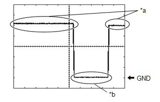
CHECK ID CODE BOX (IMMOBILISER CODE ECU)
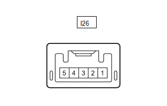
(a) Disconnect the I26 ID code box (immobiliser code ECU) connector.
(b) Measure the voltage and resistance according to the value(s) in the table below.
| Terminal No. (Symbol) | Input/Output | Wiring Color | Terminal Description | Condition | Specified Condition | Related Data List Item/DTC |
|---|---|---|---|---|---|---|
| I26-1 (+B) - Body ground | Input | B - Body ground | +B power supply | Power switch off | 11 to 14 V | B2789 |
| I26-5 (GND) - Body ground | - | W-B - Body ground | Ground | Always | Below 1 Ω | B2789 |
(c) Reconnect the I26 ID code box (immobiliser code ECU) connector.
(d) Measure the voltage and check for pulses according to the value(s) in the table below.
| Terminal No. (Symbol) | Input/Output | Wiring Color | Terminal Description | Condition | Specified Condition | Related Data List Item/DTC |
|---|---|---|---|---|---|---|
| I26-3 (EFII) - I26-5 (GND) | Input | LG - W-B | EFI communication input (Signal input from hybrid vehicle control ECU to ID code box (immobiliser code ECU)) | Power switch off | 11 to 14 V |
|
| I26-4 (EFIO) - I26-5 (GND) | Output | P - W-B | EFI communication output (Signal output from ID code box (immobiliser code ECU) to hybrid vehicle control ECU) | Power switch off | 11 to 14 V | |
| I26-3 (EFII) - I26-5 (GND) | Input | LG - W-B | EFI communication input (Signal input from hybrid vehicle control ECU to ID code box (immobiliser code ECU)) | Within 3 seconds of hybrid control system start or within 3 seconds of power switch turned on (IG) after auxiliary battery cable disconnected and reconnected | Pulse generation (See waveform 1) | |
| I26-4 (EFIO) - I26-5 (GND) | Output | P - W-B | EFI communication output (Signal output from ID code box (immobiliser code ECU) to hybrid vehicle control ECU) | Within 3 seconds of hybrid control system start or within 3 seconds of power switch turned on (IG) after auxiliary battery cable disconnected and reconnected | Pulse generation (See waveform 2) |
(e) Using an oscilloscope, check the waveform.
NOTICE:
The waveform shown in the illustration is an example for reference only. Noise, chattering, etc. are not shown.
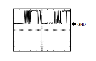
(1) Waveform 1 (Reference)
| *a | Approximately 160 ms | *b | Approximately 270 ms |
| Item | Content |
|---|---|
| Tester Connection | I26-3 (EFII) - I26-5 (GND) |
| Tool Setting | 2 V/DIV., 500 ms./DIV. |
| Condition | Within 3 seconds of hybrid control system start or within 3 seconds of power switch turned on (IG) after auxiliary battery cable disconnected and reconnected |
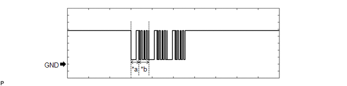
(2) Waveform 2 (Reference)
| *a | Approximately 160 ms | *b | Approximately 270 ms |
| Item | Content |
|---|---|
| Tester Connection | I26-4 (EFIO) - I26-5 (GND) |
| Tool Setting | 2 V/DIV., 500 ms./DIV. |
| Condition | Within 3 seconds of hybrid control system start or within 3 seconds of power switch turned on (IG) after auxiliary battery cable disconnected and reconnected |
CHECK STEERING LOCK ECU (STEERING LOCK ACTUATOR ASSEMBLY)
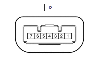
(a) Measure the voltage and resistance and check for pulses according to the value(s) in the table below.
| Terminal No. (Symbol) | Input/Output | Wiring Color | Terminal Description | Condition | Specified Condition | Related Data List Item/DTC |
|---|---|---|---|---|---|---|
| I2-1 (GND) - Body ground | - | W-B - Body ground | Ground | Always | Below 1 Ω | - |
| I2-3 (IGE) - I2-1 (GND) | Input | L - W-B | Steering lock motor operation permission signal (motor operation permission signal supplied by certification ECU (smart key ECU assembly)) | Steering lock motor operates when both conditions met, and then door opened:
| Pulse generation (See waveform 1) |
|
| I2-4 (SLP1) - I2-1 (GND) | Output | Y - W-B | Steering lock bar position signal (signal output from steering unlock sensor) | Steering locked → unlocked* | 11 to 14 V → Below 1.5 V | Sensor Value |
| I2-6 (IG2) - I2-1 (GND) | Input | P - W-B | IG signal (IG2 power supply input for steering lock motor) | Power switch off → on (IG) | Below 1 V → 11 to 14 V | B2788 |
| I2-7 (B) - Body ground | Input | L - Body ground | Constant power supply | Power switch off | 11 to 14 V | B2788 |
HINT:
*: The steering locks when any door is opened with the shift lever in P and the power switch off. The steering unlocks when the power switch is turned on (ACC).
(b) Using an oscilloscope, check the waveform.
NOTICE:
The waveform shown in the illustration is an example for reference only. Noise, chattering, etc. are not shown.
(1) Waveform 1 (Reference)
| *a | Steering lock motor not operating |
| *b | Steering lock motor operating |
| Item | Content |
|---|---|
| Tester Connection | I2-3 (IGE) - I2-1 (GND) |
| Tool Setting | 2 V/DIV., 200 ms./DIV. |
| Condition | Steering lock motor operates when both conditions met, and then door opened:
|
CHECK HYBRID VEHICLE CONTROL ECU
(a) Measure the voltage and resistance and check for pulses according to the value(s) in the table below.
| Terminal No. (Symbol) | Input/Output | Wiring Color | Terminal Description | Condition | Specified Condition | Related Data List Item/DTC |
|---|---|---|---|---|---|---|
| A60-1 (+B2) - I115-6 (E1) | Input | P - W-B | Ignition power supply | Power switch on (IG) | 11 to 14 V | - |
| A61-4 (+B1) - I115-6 (E1) | Input | V - W-B | Ignition power supply | Power switch on (IG) | 11 to 14 V | - |
| A61-6 (MREL) - I115-6 (E1) | Output | B - W-B | Ignition power supply | Power switch on (IG) | 11 to 14 V | - |
| I115-5 (E01) - Body ground | - | W-B - Body ground | Ground | Always | Below 1 Ω | - |
| I115-6 (E1) - Body ground | - | W-B - Body ground | Ground | Always | Below 1 Ω | - |
| I116-4 (E12) - Body ground | - | W-B - Body ground | Ground | Always | Below 1 Ω | - |
| I116-5 (E02) - Body ground | - | W-B - Body ground | Ground | Always | Below 1 Ω | - |
| I116-3 (BATT) - I115-6 (E1) | Input | R - W-B | +B power supply | Power switch off | 11 to 14 V | - |
| I116-23 (IMO) - I115-6 (E1) | Output | LG - W-B | ID code box (immobiliser code ECU) communication output | Power switch off | 11 to 14 V | - |
| I116-23 (IMO) - I115-6 (E1) | Output | LG - W-B | ID code box (immobiliser code ECU) communication output | Within 3 seconds of hybrid control system start or within 3 seconds of power switch turned on (IG) after auxiliary battery cable disconnected and reconnected | Pulse generation (See waveform 1) | - |
| I116-22 (IMI) - I115-6 (E1) | Input | P - W-B | ID code box (immobiliser code ECU) communication input | Power switch off | 11 to 14 V | - |
| I116-22 (IMI) - I115-6 (E1) | Input | P - W-B | ID code box (immobiliser code ECU) communication input | Within 3 seconds of hybrid control system start or within 3 seconds of power switch turned on (IG) after auxiliary battery cable disconnected and reconnected | Pulse generation (See waveform 2) | - |
(b) Using an oscilloscope, check the waveform.
NOTICE:
The waveform shown in the illustration is an example for reference only. Noise, chattering, etc. are not shown.
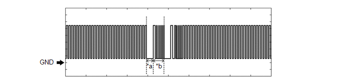
(1) Waveform 1 (Reference)
| *a | Approximately 160 ms | *b | Approximately 270 ms |
| Item | Content |
|---|---|
| Tester Connection | I116-23 (IMO) - I115-6 (E1) |
| Tool Setting | 2 V/DIV., 500 ms./DIV. |
| Condition | Within 3 seconds of hybrid control system start or within 3 seconds of power switch turned on (IG) after auxiliary battery cable disconnected and reconnected |
(2) Waveform 2 (Reference)
| *a | Approximately 160 ms | *b | Approximately 270 ms |
| Item | Content |
|---|---|
| Tester Connection | I116-22 (IMI) - I115-6 (E1) |
| Tool Setting | 2 V/DIV., 500 ms./DIV. |
| Condition | Within 3 seconds of hybrid control system start or within 3 seconds of power switch turned on (IG) after auxiliary battery cable disconnected and reconnected |
READ NEXT:
 Diagnosis System
DIAGNOSIS SYSTEM DESCRIPTION (a) The certification ECU (smart key ECU assembly) and hybrid vehicle control ECU control the vehicle immobiliser system functions. Immobiliser system data and Diagnostic
Dtc Check / Clear
DTC CHECK / CLEAR NOTICE: When using the Techstream with the power switch off, connect the Techstream to the DLC3 and turn a courtesy light switch on and off at intervals of 1.5 seconds or less until
Data List / Active Test
DATA LIST / ACTIVE TEST DATA LIST NOTICE: In the table below, the values listed under "Normal Condition" are reference values. Do not depend solely on these reference values when deciding whether a pa
SEE MORE:
"CHK" message(s) are displayed on the SIGNAL CHECK screen.
DESCRIPTION On the SIGNAL CHECK screen, it is possible to check if the signals sent to the parking assist ECU are normal. Click here HINT:
On the SIGNAL CHECK screen, "OK" (blue) is displayed for items with a normal inspection result or input state.
On the SIGNAL CHECK screen, "CHK" (red) is
Taillight Relay Circuit
DESCRIPTION Illumination of the taillights and license plate light is controlled by the main body ECU (multiplex network body ECU). WIRING DIAGRAM CAUTION / NOTICE / HINT NOTICE:
Inspect the fuses for circuits related to this system before performing the following procedure.
Recognition code
© 2016-2026 Copyright www.lexunx.com
