- Power switch on (IG)
- Intuitive parking assist system on
Lexus NX: Terminals Of Ecu
TERMINALS OF ECU
CLEARANCE WARNING ECU ASSEMBLY

(a) Disconnect the I20 clearance warning ECU assembly connector.
(b) Measure the voltage and resistance on the wire harness side connector according to the value(s) in the table below.
| Terminal No. (Symbol) | Wiring Color | Terminal Description | Condition | Specified Condition |
|---|---|---|---|---|
| I20-1 (IG) - I20-30 (E) | BE - W-B | IG power source signal | Power switch off | Below 1 V |
| Power switch on (IG) | 11 to 14 V | |||
| I20-30 (E) - Body ground | W-B - Body ground | Ground | Always | Below 1 Ω |
(c) Reconnect the I20 clearance warning ECU assembly connector.
(d) Measure the voltage, resistance and check for pulses according to the value(s) in the table below.
| Terminal No. (Symbol) | Wiring Color | Terminal Description | Condition | Specified Condition |
|---|---|---|---|---|
| I20-4 (BOF) - I20-30 (E) | R - W-B | Power source for front sensor circuit | Power switch off | Below 1 V |
| | 11 to 14 V | |||
| I20-6 (E5) - I20-30 (E) | LG - W-B | Ground for front clearance sonar | Always | Below 1 Ω |
| I20-8 (SOF) - I20-30 (E) | V - W-B | Front sensor communication signal (Front clearance sonar sensor) |
| Pulse generation (Refer to waveform 1) |
| I20-14 (CBZ) - I20-13 (EF) | LG - L | No. 1 clearance warning buzzer signal | Buzzer sounding | Pulse generation (Refer to waveform 2) |
| I20-15 (BBZ) - I20-16 (ER) | SB - P | No. 2 clearance warning buzzer signal | Buzzer sounding | (Refer to waveform 2) |
| I20-22 (BOR) - I20-30 (E) | SB - W-B | Power source for rear sensor circuit | Power switch off | Below 1 V |
| 11 to 14 V | |||
| I20-23 (E1) - I20-30 (E) | L - W-B | Ground for rear clearance sonar | Always | Below 1 Ω |
| I20-24 (SOR) - I20-30 (E) | R - W-B | Rear sensor communication signal (Rear clearance sonar sensor) |
| Pulse generation (Refer to waveform 1) |
| I20-28 (STP) - I20-30 (E)* | R - W-B | Reverse signal input |
| 11 to 14 V |
| Below 1 V | |||
| I20-31 (IND) - I20-30 (E)* | V - W-B | Reverse signal output |
| Below 3 V |
| 8 V or higher |
- *: for 10.3 Inch Display and w/ Parking Assist Monitor System
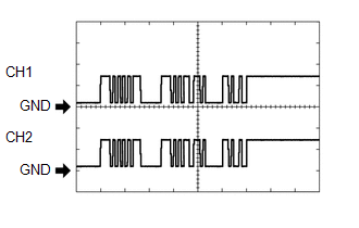
(e) Using an oscilloscope, check waveform 1.
(1) Waveform 1 (Reference)
| Item | Content |
|---|---|
| Measurement terminal |
|
| Measurement setting | 5 V/DIV., 1 ms./DIV. |
| Condition |
|
HINT:
The waveforms for CH1 and CH2 are same.
(f) Using an oscilloscope, check waveform 2.
(1) Waveform 2 (Reference)
.png)
| Item | Content |
|---|---|
| Measurement terminal | I20-14 (CBZ) - I20-13 (EF) I20-15 (BBZ) - I20-16 (ER) |
| Measurement setting | 2 V/DIV., 500 μs./DIV. |
| Condition | Buzzer sounding |
HINT:
The amplitude of the waveform changes according to the set volume.
READ NEXT:
 Diagnosis System
DIAGNOSIS SYSTEM DESCRIPTION (a) When troubleshooting a vehicle with a diagnosis system, the only difference from the usual troubleshooting procedure is connecting the Techstream to the vehicle and re
Dtc Check / Clear
DTC CHECK / CLEAR CHECK DTC (a) Connect the Techstream to the DLC3. (b) Turn the power switch on (IG). (c) Turn the intuitive parking assist system on. (d) Turn the Techstream on. (e) Enter the follow
Data List / Active Test
DATA LIST / ACTIVE TEST DATA LIST NOTICE: In the table below, the values listed under "Normal Condition" are reference values. Do not depend solely on these reference values when deciding whether a pa
SEE MORE:
Data List / Active Test
DATA LIST / ACTIVE TEST NOTICE: In the table below, the values listed under "Normal Condition" are reference values. Do not depend solely on these reference values when deciding whether a part is faulty or not. HINT: Using the Techstream to read the Data List allows the values or states of switches,
Speed Signal Circuit
DESCRIPTION The combination meter assembly receives the vehicle speed signal from this circuit. The wheel speed sensors produce an output that varies according to the vehicle speed. The wheel speed sensor output is received by the brake booster with master cylinder assembly (skid control ECU) which
© 2016-2026 Copyright www.lexunx.com
