- P45-29 (CV+) - P45-31 (SGND)
- P45-10 (LCV+) - P45-11 (SGND)
- P45-36 (BCV+) - P45-14 (SGND)
- P45-38 (RCV+) - P45-39 (SGND)
Lexus NX: Terminals Of Ecu
Lexus NX Service Manual / Audio & Visual & Telematics / Park Assist / Monitoring / Panoramic View Monitor System / Terminals Of Ecu
TERMINALS OF ECU
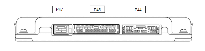
PARKING ASSIST ECU
(a) Disconnect the P44 parking assist ECU connector.
(b) Measure the voltage and resistance according to the value(s) in the table below.
| Terminal No. (Symbol) | Wiring Color | Terminal Description | Condition | Specified Condition |
|---|---|---|---|---|
| P44-1 (+B) - P44-4 (GND1) | L - W-B | Power source signal | Power switch off | 11 to 14 V |
| P44-4 (GND1) - Body ground | W-B - Body ground | Ground | Always | Below 1 Ω |
| P44-3 (IG) - P44-4 (GND1) | G - W-B | IG power source signal | Power switch on (IG) | 11 to 14 V |
| Power switch off | Below 1 V | |||
| P44-2 (ACC) - P44-4 (GND1) | L - W-B | ACC power source signal | Power switch on (ACC) | 11 to 14 V |
| Power switch off | Below 1 V |
(c) Reconnect the P44 parking assist ECU connector.
(d) Measure the voltage, resistance and waveform according to the value(s) in the table below.
| Terminal No. (Symbol) | Wiring Color | Terminal Description | Condition | Specified Condition |
|---|---|---|---|---|
| P45-29 (CV+) - P45-31 (SGND) | W - Shielded | Rear television camera assembly display signal input | Power switch on (IG), No. 2 combination switch assembly (panoramic view monitor main switch) on, camera lens not covered, displaying image | Pulse generation (See waveform 1) |
| Power switch on (IG), No. 2 combination switch assembly (panoramic view monitor main switch) on, camera lens covered, blacking out screen | Pulse generation (See waveform 2) | |||
| P45-33 (CB+) - P45-31 (SGND) | B - Shielded | Power source to rear television camera | Power switch on (IG) | 5.5 to 7.05 V |
| P45-6 (RSW+) - P44-4 (GND1) | P - W-B | Terminal required by law | Panoramic image being displayed | 0 to 2 V |
| Panoramic image not being displayed | 5.5 to 7.05 V | |||
| P44-15 (BLSW) - Body ground | R - Body ground | No. 2 combination switch assembly (panoramic view monitor main switch) switch signal | Power switch on (IG), No. 2 combination switch assembly (panoramic view monitor main switch) off | 5.5 to 6.5 V |
| Power switch on (IG), No. 2 combination switch assembly (panoramic view monitor main switch) on | Below 1 V | |||
| P45-31 (SGND) - P44-4 (GND1) | Shielded - W-B | Rear television camera assembly ground (shield) | Always | Below 1 Ω |
| P45-30 (CV-) - P45-31 (SGND) | R - Shielded | Rear television camera assembly ground | Always | Below 1 Ω |
| P45-34 (LCV-) - P45-11 (SGND) | W - Shielded | Side television camera assembly LH ground | Always | Below 1 Ω |
| P45-10 (LCV+) - P45-35 (LGND) | R - G | Side television camera assembly LH display signal input | Power switch on (IG), No. 2 combination switch assembly (panoramic view monitor main switch) on, camera lens not covered, displaying image | Pulse generation (See waveform 1) |
| Power switch on (IG), No. 2 combination switch assembly (panoramic view monitor main switch) on, camera lens covered, blacking out screen | Pulse generation (See waveform 2) | |||
| P45-11 (SGND) - P44-4 (GND1) | Shielded - W-B | Side television camera assembly LH ground (shield) | Always | Below 1 Ω |
| P45-12 (LCB+) - P45-11 (SGND) | B - Shielded | Power source to side television camera assembly LH | Power switch on (IG) | 5.5 to 7.05 V |
| P45-13 (BCV-) - P45-14 (SGND) | W - Shielded | Front television camera assembly ground | Always | Below 1 Ω |
| P45-36 (BCV+) - P45-14 (SGND) | R - Shielded | Front television camera assembly display signal input | Waveform 1: Power switch on (IG), No. 2 combination switch assembly (panoramic view monitor main switch) on, camera lens not covered, displaying image | Pulse generation (See waveform 1) |
| Waveform 2: Power switch on (IG), No. 2 combination switch assembly (panoramic view monitor main switch) on, camera lens covered, blacking out screen | Pulse generation (See waveform 2) | |||
| P45-14 (SGND) - P44-4 (GND1) | Shielded - W-B | Front television camera assembly ground (shield) | Always | Below 1 Ω |
| P45-15 (BCB+) - P45-14 (SGND) | B - Shielded | Power source to front television camera | Power switch on (IG) | 5.5 to 7.05 V |
| P45-16 (RCV-) - P45-39 (SGND) | W - Shielded | Side television camera assembly RH ground | Always | Below 1 Ω |
| P45-38 (RCV+) - P45-39 (SGND) | R - Shielded | Side television camera assembly RH display signal input | Waveform 1: Power switch on (IG), No. 2 combination switch assembly (panoramic view monitor main switch) on, camera lens not covered, displaying image | Pulse generation (See waveform 1) |
| Waveform 2: Power switch on (IG), No. 2 combination switch assembly (panoramic view monitor main switch) on, camera lens covered, blacking out screen | Pulse generation (See waveform 2) | |||
| P45-39 (SGND) - P44-4 (GND1) | Shielded - W-B | Side television camera assembly RH ground (shield) | Always | Below 1 Ω |
| P45-40 (RCB+) - P45-39 (SGND) | B - Shielded | Power source to side television camera assembly RH | Power switch on (IG) | 5.5 to 7.05 V |
(e) Using an oscilloscope, check the waveform.
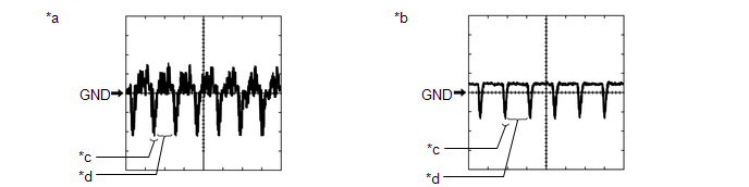
| *a | Waveform 1 | *b | Waveform 2 |
| *c | Synchronization Signal | *d | Video Waveform |
(1) Waveform 1
Measurement Condition| Item | Content |
|---|---|
| Terminal No. (Symbol) | |
| Tool Setting | 200 mV/DIV., 50 μsec./DIV. |
| Condition |
|
HINT:
- The video waveform changes according to the image sent by the television camera assembly.
- The video waveform is constantly output when the power switch is on (ACC).
RADIO RECEIVER ASSEMBLY (w/ Audio and Visual System)
Click here .gif)
RADIO RECEIVER ASSEMBLY (w/ Navigation System)
Click here
READ NEXT:
 Diagnosis System
DIAGNOSIS SYSTEM PARKING ASSIST MONITOR DIAGNOSIS SYSTEM (a) For panoramic view monitor system diagnosis, signals received by the parking assist ECU can be checked, and the panoramic view monitor syst
Dtc Check / Clear
DTC CHECK / CLEAR CHECK DTC (a) Connect the Techstream to the DLC3. (b) Turn the power switch on (IG). (c) Turn the Techstream on. (d) Enter the following menus: Chassis / Panoramic View Monitor / Tro
Data List / Active Test
DATA LIST / ACTIVE TEST DATA LIST HINT: Using the Techstream to read the Data List allows the values or states of switches, sensors, actuators and other items to be read without removing any parts. Th
SEE MORE:
Shift Paddle Switch Circuit
DESCRIPTION When the shift lever is in S, the shift range position can be changed freely using the shift paddle switch of the transmission shift switch assembly. WIRING DIAGRAM PROCEDURE 1. READ VALUE USING TECHSTREAM (SPORT UP SHIFT SENS STATE, SPORT DWN SHIFT SENS STATE) (a) Connect the
Fail-safe Chart
FAIL-SAFE CHART If any of the following DTCs are stored, the ECM enters fail-safe mode to allow the vehicle to be driven temporarily or stops fuel injection. DTC Code Component Fail-Safe Operation Fail-Safe Deactivation Condition P0031 P0032 P101D Air fuel ratio sensor heater The EC
© 2016-2026 Copyright www.lexunx.com
