Lexus NX: Shift Paddle Switch Circuit
DESCRIPTION
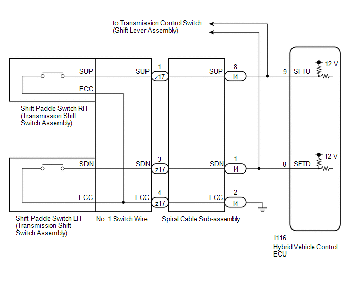
When the shift lever is in S, the shift range position can be changed freely using the shift paddle switch of the transmission shift switch assembly.
WIRING DIAGRAM
PROCEDURE
| 1. | READ VALUE USING TECHSTREAM (SPORT UP SHIFT SENS STATE, SPORT DWN SHIFT SENS STATE) |
(a) Connect the Techstream to the DLC3.
(b) Turn the power switch on (IG).
(c) Enter the following menus: Powertrain / Hybrid Control / Data List / Sport Up Shift Sens State, Sport Dwn Shift Sens State.
Powertrain > Hybrid Control > Data List| Tester Display |
|---|
| Sport Up Shift Sens State |
| Sport Dwn Shift Sens State |
(d) Read the value displayed on the Techstream.
Powertrain > Hybrid Control > Data List| Tester Display | Measurement Item | Range | Normal Condition |
|---|---|---|---|
| Sport Up Shift Sens State | Sports shift UP signal | ON or OFF | shift paddle switch RH operated: ON shift paddle switch RH not operated: OFF |
| Sport Dwn Shift Sens State | Sport shift DOWN signal | ON or OFF | shift paddle switch LH operated: ON shift paddle switch LH not operated: OFF |
| Result | Proceed to |
|---|---|
| The Techstream display changes according to the shift paddle switch (transmission shift switch assembly) operation. | A |
| The Techstream display does not change according to the shift paddle switch (transmission shift switch assembly) operation. | B |
| A | .gif) | CHECK FOR INTERMITTENT PROBLEMS |
|
.gif)
| 2. | CHECK HARNESS AND CONNECTOR (SPIRAL CABLE SUB-ASSEMBLY - HYBRID VEHICLE CONTROL ECU) |
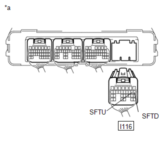
(a) Disconnect the I116 hybrid vehicle control ECU connector.
(b) Disconnect the I23 transmission control switch (shift lever assembly ) connector.
| (c) Measure the resistance according to the value(s) in the table below when the shift paddle switch (transmission shift switch assembly) is moved to each position. Standard Resistance:
|
|
(d) Reconnect the I23 transmission control switch (shift lever assembly ) connector.
(e) Reconnect the I116 hybrid vehicle control ECU connector.
| OK | | REPLACE HYBRID VEHICLE CONTROL ECU |
|
| 3. | CHECK HARNESS AND CONNECTOR (SPIRAL CABLE SUB-ASSEMBLY - BODY GROUND) |
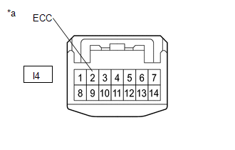
| (a) Disconnect the I4 spiral cable sub-assembly connector. |
|
(b) Measure the resistance according to the value(s) in the table below.
Standard Resistance (Open):
| Tester Connection | Condition | Specified Condition |
|---|---|---|
| I4-2 (ECC) - Body ground | Always | Below 1 Ω |
(c) Reconnect the I4 spiral cable sub-assembly connector.
| NG | | REPAIR OR REPLACE HARNESS OR CONNECTOR |
|
| 4. | INSPECT SPIRAL CABLE SUB-ASSEMBLY |
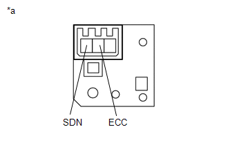
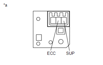
(a) Remove the spiral cable sub-assembly.
Click here .gif)
| *a | Component without harness connected (Spiral Cable Sub-assembly) | - | - |
(b) Set the spiral cable sub-assembly to the center position.
Click here
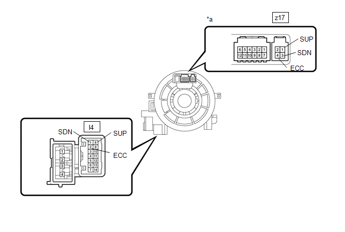
(c) Measure the resistance between the terminals of the spiral cable sub-assembly according to the value(s) in the table below.
- After setting the spiral cable sub-assembly to the center position, rotate the spiral cable sub-assembly 2.5 times clockwise and measure the resistance. Then rotate the spiral cable sub-assembly 2.5 times counterclockwise and measure the resistance.
- After setting the spiral cable sub-assembly to the center position, rotate the spiral cable sub-assembly 2.5 times clockwise. Then while rotating the spiral cable sub-assembly 5 times counterclockwise, measure the resistance.
Standard Resistance:
| Tester Connection | Condition | Specified Condition |
|---|---|---|
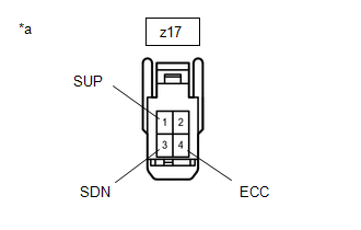
| z17-1 (SUP) - I4-8 (SUP) | Always | Below 1 Ω |
| z17-3 (SDN) - I4-1 (SDN) | Always | Below 1 Ω |
| z17-4 (ECC) - I4-2 (ECC) | Always | Below 1 Ω |
NOTICE:
As the spiral cable sub-assembly may break, do not rotate the spiral cable sub-assembly more than the specified amount.
(d) Install the spiral cable sub-assembly.
| NG | | REPLACE SPIRAL CABLE SUB-ASSEMBLY |
|
| 5. | INSPECT SHIFT PADDLE SWITCH (TRANSMISSION SHIFT SWITCH ASSEMBLY) LH |
(a) Remove the shift paddle switch (transmission shift switch assembly) LH.
Click here
| (b) Measure the resistance according to the value(s) in the table below when the shift paddle switch (transmission shift switch assembly) is moved to each position. Standard Resistance:
|
|
(c) Install the shift paddle switch (transmission shift switch assembly) LH.
| NG | | REPLACE SHIFT PADDLE SWITCH (TRANSMISSION SHIFT SWITCH ASSEMBLY) LH |
|
| 6. | INSPECT SHIFT PADDLE SWITCH (TRANSMISSION SHIFT SWITCH ASSEMBLY) RH |
(a) Remove the shift paddle switch (transmission shift switch assembly) RH.
Click here
| (b) Measure the resistance according to the value(s) in the table below when the shift paddle switch (transmission shift switch assembly) is moved to each position. Standard Resistance:
|
|
(c) Install the shift paddle switch (transmission shift switch assembly) RH.
| NG | | REPLACE SHIFT PADDLE SWITCH (TRANSMISSION SHIFT SWITCH ASSEMBLY) RH |
|
| 7. | INSPECT NO. 1 SWITCH WIRE |
(a) Disconnect the z17 No. 1 switch wire connector.
| (b) Measure the resistance according to the value(s) in the table below when the shift paddle switch (transmission shift switch assembly) is moved to each position. Standard Resistance:
|
|
(c) Reconnect the z17 No. 1 switch wire connector.
| OK | | REPAIR OR REPLACE HARNESS OR CONNECTOR |
| NG | | REPLACE NO. 1 SWITCH WIRE |
READ NEXT:
 Pattern Select Switch EV Mode Circuit
DESCRIPTION The EV drive mode signal will be sent to the hybrid vehicle control ECU when the EV drive mode switch (integration control & panel assembly) is operated. If the specified conditions ar
Pattern Select Switch Sport Mode Circuit
DESCRIPTION When selecting SPORT mode, the switch operation signal is sent to the ECM. Following this, the drive torque is optimally controlled to obtain a sporty feel in response to the driver's acce
Pattern Select Switch Eco Mode Circuit
DESCRIPTION When selecting ECO mode, the mode switch (integration control & panel assembly) operation signal is sent to the air conditioning amplifier assembly. Following this, ECO mode control is
SEE MORE:
Airbag ECU Malfunction (B1000)
DESCRIPTION The airbag ECU assembly consists of a deceleration sensor, safing sensor, drive circuit, diagnosis circuit, ignition control, etc. If the airbag ECU assembly receives signals from the deceleration sensor, it determines whether or not the SRS should be activated. DTC B1000 is stored when
Installation
INSTALLATION CAUTION / NOTICE / HINT HINT:
Use the same procedure for the RH and LH sides.
The procedure listed below is for the LH side.
PROCEDURE 1. REPAIR INSTRUCTION (a) Clean the vehicle body surface. (1) Using a heat light, heat the vehicle body surface. (2) Wipe off any tape adhesive
