- DTC judgment completed
- System normal
Lexus NX: Throttle Actuator Control System - Stuck Open (P2111,P2112)
Lexus NX Service Manual / Engine & Hybrid System / 2ar-fxe (engine Control) / Sfi System / Throttle Actuator Control System - Stuck Open (P2111,P2112)
DESCRIPTION
The throttle actuator is operated by the ECM, and opens and closes the throttle valve using gears. The opening angle of the throttle valve is detected by the throttle position sensor, which is mounted on the throttle body with motor assembly. The throttle position sensor provides feedback to the ECM. This feedback allows the ECM to appropriately control the throttle actuator and monitor the throttle opening angle as the ECM responds to a request from the hybrid system.
HINT:
This Electronic Throttle Control System (ETCS) does not use a throttle cable.
| DTC No. | Detection Item | DTC Detection Condition | Trouble Area | MIL | Memory |
|---|---|---|---|---|---|
| P2111 | Throttle Actuator Control System - Stuck Open | The ECM signals the throttle actuator to close, but the actuator is stuck (1 trip detection logic). |
| Comes on | DTC stored |
| P2112 | Throttle Actuator Control System - Stuck Closed | The ECM signals the throttle actuator to open, but the actuator is stuck (1 trip detection logic). |
| Comes on | DTC stored |
MONITOR DESCRIPTION
The ECM determines that there is a malfunction in the ETCS when the throttle valve remains at a fixed angle despite a high drive current from the ECM. The ECM then illuminates the MIL and stores a DTC.
MONITOR STRATEGY
| Related DTCs | P2111: Throttle actuator stuck open P2112: Throttle actuator stuck closed |
| Required Sensors/Components (Main) | Throttle actuator (throttle body with motor assembly) |
| Required Sensors/Components (Related) | - |
| Frequency of Operation | Continuous |
| Duration | 0.5 seconds |
| MIL Operation | Immediate |
| Sequence of Operation | None |
TYPICAL ENABLING CONDITIONS
All| Monitor runs whenever the following DTCs are not stored | None |
| All of the following conditions are met | - |
| System guard* judge condition | On |
| Throttle actuator current | 2 A or higher |
| Duty-cycle to close throttle | 80% or higher |
| All of the following conditions are met | - |
| System guard* judge condition | On |
| Throttle actuator current | 2 A or higher |
| Duty-cycle to open throttle | 80% or higher |
| *: System guard is on when the following conditions are met | - |
| Throttle actuator | On |
| Throttle actuator duty calculation | Executing |
| Throttle position sensor fail | Not detected |
| Throttle actuator current-cut operation | Not executing |
| Throttle actuator power supply | 4 V or higher |
| Throttle actuator fail | Not detected |
TYPICAL MALFUNCTION THRESHOLDS
P2111: Throttle Actuator Stuck Open| Throttle position sensor voltage | No change |
| Throttle position sensor voltage | No change |
CONFIRMATION DRIVING PATTERN
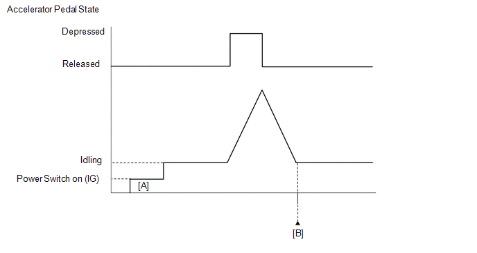
- Connect the Techstream to the DLC3.
- Turn the power switch on (IG) and turn the Techstream on.
- Clear the DTCs (even if no DTCs are stored, perform the clear DTC procedure).
- Turn the power switch off and wait for at least 30 seconds.
- Turn the power switch on (IG) and turn the Techstream on [A].
-
Put the engine in inspection mode (maintenance mode).
Click here
.gif)
- Start the engine and fully depress and release the accelerator pedal quickly (to fully open and close the throttle valve).
- Enter the following menus: Powertrain / Engine and ECT / Trouble Codes [B].
-
Read the pending DTCs.
HINT:
- If a pending DTC is output, the system is malfunctioning.
- If a pending DTC is not output, perform the following procedure.
- Enter the following menus: Powertrain / Engine and ECT / Utility / All Readiness.
- Input the DTC: P2111 or P2112.
-
Check the DTC judgment result.
Techstream Display
Description
NORMAL
ABNORMAL
- DTC judgment completed
- System abnormal
INCOMPLETE
- DTC judgment not completed
- Perform driving pattern after confirming DTC enabling conditions
N/A
- Unable to perform DTC judgment
- Number of DTCs which do not fulfill DTC preconditions has reached ECU memory limit
HINT:
- If the judgment result shows NORMAL, the system is normal.
- If the judgment result shows ABNORMAL, the system has a malfunction.
-
If the judgment result is INCOMPLETE or N/A and no pending DTC is output, perform a universal trip and check for permanent DTCs.
Click here
HINT:
- If a permanent DTC is output, the system is malfunctioning.
- If no permanent DTC is output, the system is normal.
FAIL-SAFE
When either of these DTCs or other DTCs relating to Electronic Throttle Control System (ETCS) malfunctions are stored, the ECM enters fail-safe mode. During fail-safe mode, the ECM cuts the current to the throttle actuator, and the throttle valve is returned to a 5.5° throttle valve opening angle by the return spring. The ECM stops the engine and the vehicle can be driven using solely the hybrid system. If the accelerator pedal is depressed firmly and gently, the vehicle can be driven slowly.
Fail-safe mode continues until a pass condition is detected, and the power switch is then turned off.
WIRING DIAGRAM
Refer to DTC P2102.
Click here
CAUTION / NOTICE / HINT
HINT:
-
Refer to "Data List / Active Test" [Throttle Position Command, Throttle Position No.1, Throttle Motor Current, Throttle Motor Duty (Open), Throttle Motor Duty (Close)].
Click here
- Read freeze frame data using the Techstream. The ECM records vehicle and driving condition information as freeze frame data the moment a DTC is stored. When troubleshooting, freeze frame data can help determine if the vehicle was moving or stationary, if the engine was warmed up or not, if the air fuel ratio was lean or rich, and other data from the time the malfunction occurred.
PROCEDURE
| 1. | CHECK ANY OTHER DTCS OUTPUT (IN ADDITION TO DTC P2111 OR P2112) |
(a) Connect the Techstream to the DLC3.
(b) Turn the power switch on (IG).
(c) Turn the Techstream on.
(d) Enter the following menus: Powertrain / Engine and ECT / Trouble Codes.
(e) Read the DTCs.
Powertrain > Engine and ECT > Trouble Codes| Result | Proceed to |
|---|---|
| DTC P2111 or P2112 is output | A |
| DTC P2111 or P2112 and other DTCs are output | B |
HINT:
If any DTCs other than P2111 or P2112 are output, troubleshoot those DTCs first.
| B | .gif) | GO TO DTC CHART |
|
.gif)
| 2. | INSPECT THROTTLE BODY WITH MOTOR ASSEMBLY (VISUALLY CHECK THROTTLE VALVE) |
(a) Check for contamination between the throttle valve and housing. If necessary, clean the throttle body with motor assembly. Also check that the throttle valve moves smoothly.
OK:
Throttle valve is not contaminated with foreign matter and moves smoothly.
HINT:
Perform "Inspection After Repair" after cleaning the throttle body with motor assembly.
Click here
| NG | | GO TO STEP 5 |
|
| 3. | READ VALUE USING TECHSTREAM (THROTTLE POSITION) |
(a) Connect the Techstream to the DLC3.
(b) Turn the power switch on (IG).
(c) Turn the Techstream on.
(d) Clear the DTCs.
Click here
(e) Turn the power switch off and wait for at least 30 seconds.
(f) Turn the power switch on (IG) and turn the Techstream on.
(g) Enter the following menus: Powertrain / Engine and ECT / Data List / Gas Throttle / Throttle Position No.1, Throttle Position No.2 and Throttle Position Command.
Powertrain > Engine and ECT > Data List| Tester Display |
|---|
| Throttle Position No.1 |
| Throttle Position No.2 |
| Throttle Position Command |
(h) Read the values displayed on the Techstream while wiggling the ECM wire harness.
(i) Enter the following menus: Powertrain / Engine and ECT / Trouble Codes.
(j) Read the DTCs.
Powertrain > Engine and ECT > Trouble Codes| Result | Proceed to |
|---|---|
| Value in Data List changes when wire harness is wiggled, or DTC is output | A |
| Other than above | B |
| B | | GO TO STEP 6 |
|
| 4. | REPAIR OR REPLACE HARNESS OR CONNECTOR (ECM - THROTTLE BODY WITH MOTOR ASSEMBLY) |
(a) As the DTC was stored due to a change in the contact resistance of the connector, repair or replace the wire harness or connector.
Click here
| NEXT | | END |
| 5. | REPLACE THROTTLE BODY WITH MOTOR ASSEMBLY |
(a) Replace the throttle body with motor assembly.
Click here
HINT:
Perform "Inspection After Repair" after replacing the throttle body with motor assembly.
Click here
|
| 6. | CHECK WHETHER DTC OUTPUT RECURS (DTC P2111 OR P2112) |
(a) Connect the Techstream to the DLC3.
(b) Turn the power switch on (IG).
(c) Turn the Techstream on.
(d) Clear the DTCs.
Click here
(e) Turn the power switch off and wait for at least 30 seconds.
(f) Turn the power switch on (IG).
(g) Turn the Techstream on.
(h) Drive the vehicle in accordance with the driving pattern described in Confirmation Driving Pattern.
(i) Enter the following menus: Powertrain / Engine and ECT / Trouble Codes.
(j) Read the DTCs.
Powertrain > Engine and ECT > Trouble Codes| Result | Proceed to |
|---|---|
| DTCs are not output | A |
| DTC P2111 or P2112 is output | B |
| A | | END |
| B | | REPLACE ECM |
READ NEXT:
 Throttle Actuator Control Motor Current Range / Performance (P2118)
DESCRIPTION The electronic throttle control system has a dedicated power supply circuit. The voltage (+BM) is monitored and when it is low (less than 4 V), the ECM determines that there is a malfuncti
Throttle Actuator Control Throttle Body Range / Performance (P2119)
DESCRIPTION The electronic throttle control system is composed of the throttle actuator, throttle position sensor, and ECM. The ECM operates the throttle actuator to regulate the throttle valve in res
Oxygen (A/F) Sensor Signal Stuck Lean (Bank 1 Sensor 1) (P2195,P2196)
DESCRIPTION HINT: Although the DTC titles say oxygen sensor, these DTCs relate to the air fuel ratio sensor. The air fuel ratio sensor generates voltage* that corresponds to the actual air fuel ratio.
SEE MORE:
Power Supply Drive Circuit (C1257)
DESCRIPTION The skid control ECU (brake booster with master cylinder assembly) detects a drop in accumulator pressure according to the signals from the accumulator pressure sensor, then operates and stops the motor relay as well as the pump motor. The skid control ECU (brake booster with master cyli
Do-it-yourself service precautions
If you perform maintenance by
yourself, be sure to follow the correct
procedure as given in these
sections.
Maintenance
Items
Parts and tools
12-volt battery
condition
Grease
Conventional wrench
(for terminal clamp
bolts)
Brake flui
© 2016-2026 Copyright www.lexunx.com
