Lexus NX: Tilt and Telescopic Manual Switch Circuit Malfunction (B2603)
DESCRIPTION
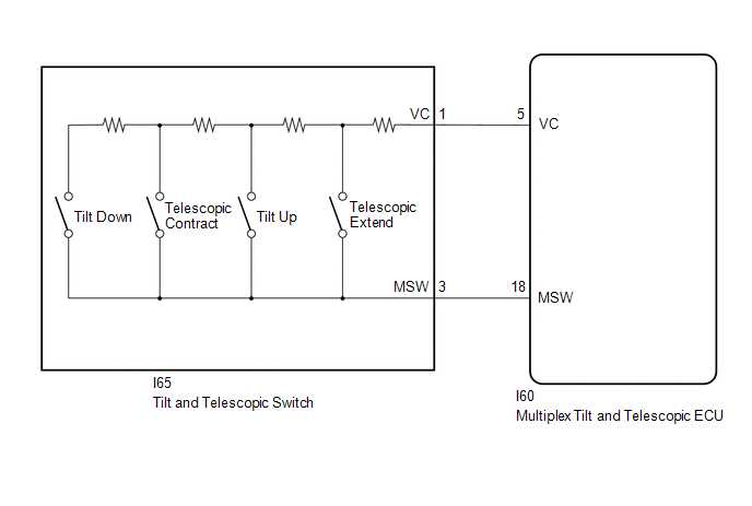
Different voltage values are sent to the multiplex tilt and telescopic ECU by operating the tilt and telescopic switch. The multiplex tilt and telescopic ECU then judges which motor and in which direction that motor should operate based on the voltage value.
| DTC No. | Detection Item | DTC Detection Condition | Trouble Area |
|---|---|---|---|
| B2603 | Tilt and Telescopic Manual Switch Circuit Malfunction | When operating the tilt and telescopic switch, an abnormal voltage value is sent to the multiplex tilt and telescopic ECU. |
|
WIRING DIAGRAM
PROCEDURE
| 1. | READ VALUE USING TECHSTREAM (TILT UP/DOWN SWITCH, TELESCOPIC SHORT/LONG SWITCH) |
(a) Turn the power switch off.
(b) Connect the Techstream to the DLC3.
(c) Turn the power switch on (IG).
(d) Turn the Techstream on.
(e) Check the tilt and telescopic switch.
(f) Enter the following menus: Body Electrical / Tilt & Telescopic / Data List.
Body Electrical > Tilt&Telescopic > Data List| Tester Display | Measurement Item | Range | Normal Condition | Diagnostic Note |
|---|---|---|---|---|
| Tilt Up Switch | Input state of tilt up switch | ON or OFF | ON: Tilt up switch activated OFF: Tilt up switch not activated | - |
| Tilt Down Switch | Input state of tilt down switch | ON or OFF | ON: Tilt down switch activated OFF: Tilt down switch not activated | - |
| Telesco Short Switch | Input state of telescopic contract switch | ON or OFF | ON: Telescopic contract switch activated OFF: Telescopic contract switch not activated | - |
| Telesco Long Switch | Input state of telescopic extend switch | ON or OFF | ON: Telescopic extend switch activated OFF: Telescopic extend switch not activated | - |
| Tester Display |
|---|
| Tilt Up Switch |
| Tilt Down Switch |
| Telesco Short Switch |
| Telesco Long Switch |
OK:
"ON" is displayed on the Techstream screen when each switch is turned on.
"OFF" is displayed on the Techstream screen when each switch is turned off.
| NG | .gif) | GO TO STEP 3 |
|
.gif)
| 2. | CONFIRM DTC |
(a) Clear the DTCs.
Click here .gif)
(b) Check for DTCs.
Click here
| Result | Proceed to |
|---|---|
| DTCs are output. | A |
| DTCs are not output. | B |
| A | | REPLACE MULTIPLEX TILT AND TELESCOPIC ECU |
| B | | USE SIMULATION METHOD TO CHECK |
| 3. | CHECK HARNESS AND CONNECTOR (MULTIPLEX TILT AND TELESCOPIC ECU - TILT AND TELESCOPIC SWITCH) |
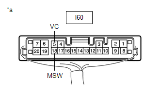
(a) Disconnect the I60 multiplex tilt and telescopic ECU connector.
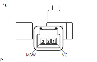
(b) Disconnect the I65 tilt and telescopic switch connector.
(c) Measure the resistance according to the value(s) in the table below.
Standard Resistance:
| Tester Connection | Condition | Specified Condition |
|---|---|---|
| I60-5 (VC) - I65-1 (VC) | Always | Below 1 Ω |
| I60-18 (MSW) - I65-3 (MSW) | Always | Below 1 Ω |
| I60-5 (VC) - Body ground | Always | 10 kΩ or higher |
| I60-18 (MSW) - Body ground | Always | 10 kΩ or higher |
| NG | | REPAIR OR REPLACE HARNESS OR CONNECTOR |
|
| 4. | CHECK MULTIPLEX TILT AND TELESCOPIC ECU (VC TERMINAL VOLTAGE) |
| (a) Reconnect the I60 multiplex tilt and telescopic ECU connector. |
|
(b) Measure the voltage according to the value(s) in the table below.
Standard Voltage:
| Tester Connection | Condition | Specified Condition |
|---|---|---|
| I60-5 (VC) - I60-18 (MSW) | Power switch on (IG) | 4.9 to 5.1 V |
| NG | | REPLACE MULTIPLEX TILT AND TELESCOPIC ECU |
|
| 5. | CHECK TILT AND TELESCOPIC SWITCH |
| (a) Remove the tilt and telescopic switch. Click here |
|
(b) Measure the resistance according to the value(s) in the table below.
Standard Resistance:
| Tester Connection | Condition | Specified Condition |
|---|---|---|
| 1 (VC) - 3 (MSW) | Tilt up | 342 to 378 Ω |
| Tilt down | 1890.5 to 2089.5 Ω | |
| Telescopic contract | 750.5 to 829.5 Ω | |
| Telescopic extend | 152 to 168 Ω |
| OK | | REPLACE MULTIPLEX TILT AND TELESCOPIC ECU |
| NG | | REPLACE TILT AND TELESCOPIC SWITCH |
READ NEXT:
 Tilt Position Sensor or Tilt Motor Circuit Malfunction (B2610)
DESCRIPTION The tilt motor is operated by the power source voltage supplied from the multiplex tilt and telescopic ECU and tilts the steering column up and down. The tilt position sensor (Hall IC) in
Telescopic Position Sensor or Telescopic Motor Circuit Malfunction (B2611)
DESCRIPTION The telescopic motor is operated by the power source voltage supplied from the multiplex tilt and telescopic ECU and slides the steering column forward and backward. The telescopic positio
ECU Power Source Circuit Malfunction (B2620)
DESCRIPTION The ECU power source circuit supplies positive (+) voltage to the multiplex tilt and telescopic ECU. DTC No. Detection Item DTC Detection Condition Trouble Area B2620 ECU Po
SEE MORE:
Headup Display Communication Stop Mode
DESCRIPTION Detection Item Symptom Trouble Area Headup Display Communication Stop Mode Any of the following conditions are met:
Communication stop for "Head Up Display" is indicated on the "Communication Bus Check" screen of the Techstream.
Click here
Communication system DTCs
Components
COMPONENTS ILLUSTRATION *1 DECK FLOOR BOX LH *2 NO. 3 DECK BOARD SUB-ASSEMBLY *3 REAR DECK FLOOR BOX *4 NEGATIVE AUXILIARY BATTERY TERMINAL N*m (kgf*cm, ft.*lbf): Specified torque - - ILLUSTRATION *1 BATTERY SERVICE HOLE COVER *2 HYBRID BATTERY SERVICE PLU
