Lexus NX: Tire Pressure Warning Initiator (for Front Side)
Components
COMPONENTS
ILLUSTRATION
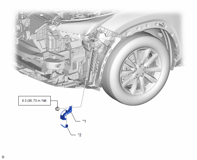
| *1 | FRONT TIRE PRESSURE MONITOR INITIATOR | *2 | CONNECTOR |
.png) | N*m (kgf*cm, ft.*lbf): Specified torque | - | - |
Removal
REMOVAL
PROCEDURE
1. PRECAUTION
CAUTION:
Be sure to read precaution thoroughly before servicing.
Click here .gif)
2. REMOVE FRONT BUMPER ASSEMBLY
Click here
3. REMOVE FRONT TIRE PRESSURE MONITOR INITIATOR
| (a) Remove the nut. |
|
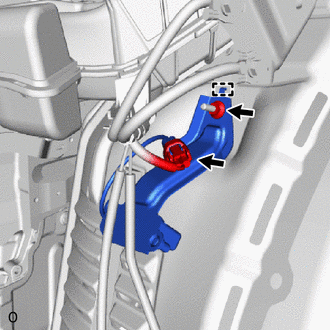
(b) Detach the guide to remove the front tire pressure monitor initiator.
(c) Disconnect the connector from the front tire pressure monitor initiator.
Installation
INSTALLATION
PROCEDURE
1. PRECAUTION
CAUTION:
Be sure to read precaution thoroughly before servicing.
Click here .gif)
2. INSTALL FRONT TIRE PRESSURE MONITOR INITIATOR
(a) Connect the connector to the front tire pressure monitor initiator.
(b) Attach the guide to temporarily install the front tire pressure monitor initiator.
(c) Install the nut.
Torque:
8.3 N·m {85 kgf·cm, 73 in·lbf}
3. INSTALL FRONT BUMPER ASSEMBLY
Click here
4. INSPECT TIRE PRESSURE WARNING SYSTEM
Click here
READ NEXT:
 Components
COMPONENTS ILLUSTRATION *1 QUARTER OUTSIDE MOULDING SUB-ASSEMBLY LH *2 REAR BUMPER SIDE SEAL LH *3 REAR TIRE PRESSURE MONITOR INITIATOR *4 REAR WHEEL HOUSE FRONT PLATE LH *5
Removal
REMOVAL PROCEDURE 1. PRECAUTION CAUTION: Be sure to read precaution thoroughly before servicing. Click here 2. REMOVE REAR WHEEL (for LH Side) Click here 3. REMOVE QUARTER OUTSIDE MOULDING SUB-ASS
SEE MORE:
Components
COMPONENTS ILLUSTRATION *1 FRONT DOOR INSIDE HANDLE BEZEL PLUG LH *2 FRONT DOOR TRIM BOARD SUB-ASSEMBLY LH *3 FRONT DOOR TRIM COVER LH *4 OUTER MIRROR INSTALL HOLE COVER LH *5 OUTER REAR VIEW MIRROR ASSEMBLY LH *6 POWER WINDOW REGULATOR MASTER SWITCH ASSEMBLY WITH FRONT
Vehicle Control History
VEHICLE CONTROL HISTORY NOTICE: Make sure to record any output Vehicle Control History codes before clearing them and checking the Vehicle Control History again. CHECK VEHICLE CONTROL HISTORY (DYNAMIC RADAR CRUISE CONTROL SYSTEM) (a) Connect the Techstream to the DLC3. (b) Turn the power switch on (
