Lexus NX: Torque Sensor1 (C1511-C1514)
DESCRIPTION
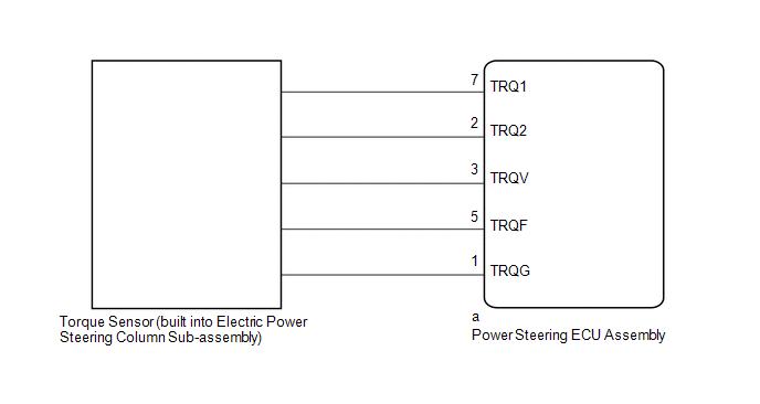
The torque sensor converts the steering wheel rotation torque into electric signals and sends them to the power steering ECU assembly.
| DTC No. | Detection Item | DTC Detection Condition | Trouble Area | Warning Indicate | Return-to-normal Condition |
|---|---|---|---|---|---|
| C1511 | Torque Sensor1 | Torque sensor malfunction |
| On | Power switch on (IG) again |
| C1512 | Torque Sensor2 | Torque sensor malfunction |
| On | Power switch on (IG) again |
| C1513 | Torque Sensor Deviation Excessive | Torque sensor malfunction |
| On | Power switch on (IG) again |
| C1514 | Torque Sensor Power Supply Voltage | Torque sensor malfunction |
| On | Power switch on (IG) again |
WIRING DIAGRAM
CAUTION / NOTICE / HINT
NOTICE:
If the power steering ECU assembly has been replaced, perform assist map writing.
Click here .gif)
PROCEDURE
| 1. | CHECK CONNECTOR CONNECTION CONDITION (TORQUE SENSOR - ECU) |
(a) Check the connection condition of the torque sensor connector.
OK:
Torque sensor connector is securely connected to the power steering ECU assembly.
| NG | .gif) | CONNECT CONNECTOR |
|
.gif)
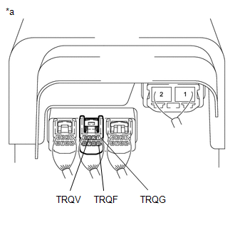
| 2. | CHECK POWER STEERING ECU ASSEMBLY (TRQV, TRQF VOLTAGE) |
| (a) Turn the power switch on (READY). |
|
(b) Measure the voltage according to the value(s) in the table below.
Standard Voltage:
| Tester Connection | Switch Condition | Specified Condition |
|---|---|---|
| a-3 (TRQV) - a-1 (TRQG) | Power switch on (READY) | 8.5 to 10.5 V |
| a-5 (TRQF) - a-1 (TRQG) | Power switch on (READY) | 3.35 to 3.37 V |
| NG | | REPLACE POWER STEERING ECU ASSEMBLY |
|
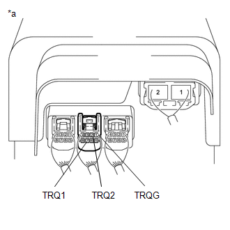
| 3. | CHECK POWER STEERING ECU ASSEMBLY (TRQ1, TRQ2 VOLTAGE) |
| (a) Turn the power switch on (READY). |
|
(b) Measure the voltage according to the value(s) in the table below.
Standard Voltage:
| Tester Connection | Condition | Specified Condition |
|---|---|---|
| a-7 (TRQ1) - a-1 (TRQG) | Power switch on (READY) Steering wheel not being turned (without load) | 2.3 to 2.7 V |
| Power switch on (READY) Steering wheel being turned to the right with vehicle stopped | 2.5 to 4.7 V | |
| Power switch on (READY) Steering wheel being turned to the left with vehicle stopped | 0.3 to 2.5 V | |
| a-2 (TRQ2) - a-1 (TRQG) | Power switch on (READY) Steering wheel not being turned (without load) | 2.3 to 2.7 V |
| Power switch on (READY) Steering wheel being turned to the right with vehicle stopped | 0.3 to 2.5 V | |
| Power switch on (READY) Steering wheel being turned to the left with vehicle stopped | 2.5 to 4.7 V |
(c) Under each condition, measure the voltage at terminals TRQ1 and TRQ2, and calculate the sum.
Standard Voltage:
| Tester Connection | Condition | Specified Condition |
|---|---|---|
| Sum of voltage between a-7 (TRQ1) and a-1 (TRQG) and voltage between a-2 (TRQ2) and a-1 (TRQG) | Power switch on (READY) Steering wheel not being turned (without load) | Between 4.85 V and 5.35 V |
| Power switch on (READY) Steering wheel being turned to the right with vehicle stopped | ||
| Power switch on (READY) Steering wheel being turned to the left with vehicle stopped |
| OK | | REPLACE POWER STEERING ECU ASSEMBLY |
| NG | | REPLACE ELECTRIC POWER STEERING COLUMN SUB-ASSEMBLY |
READ NEXT:
 Short in Motor Circuit (C1521,C1531-C1534)
DESCRIPTION DTC No. Detection Item DTC Detection Condition Trouble Area Warning Indicate Return-to-normal Condition C1521 Short in Motor Circuit Motor overcurrent Power steering
Motor Terminal Voltage (C1524,C1555)
DESCRIPTION The power steering ECU assembly supplies current to the power steering motor assembly through the motor circuit. DTC No. Detection Item DTC Detection Condition Trouble Area Warn
Motor Rotation Angle Sensor (C1528)
DESCRIPTION The motor rotation angle sensor detects the motor rotation angle and sends this information to the power steering ECU assembly. DTC No. Detection Item DTC Detection Condition Trou
SEE MORE:
Microphone Circuit
DESCRIPTION
The radio receiver assembly and telephone microphone assembly are connected to each other using the microphone connection detection signal lines.
Using this circuit, the DCM (telematics transceiver) sends power to the telephone microphone assembly, and the telephone microphone assem
Components
COMPONENTS ILLUSTRATION *A for 2WD *B for AWD *1 HOOD LOCK ASSEMBLY *2 NO. 6 INVERTER BRACKET *3 UPPER RADIATOR SUPPORT SUB-ASSEMBLY *4 FRONT RADIATOR SIDE AIR GUIDE PLATE RH *5 FRONT RADIATOR SIDE AIR GUIDE PLATE LH *6 WIRE HARNESS N*m (kgf*cm, ft.*lbf
