Lexus NX: Illumination Circuit
DESCRIPTION
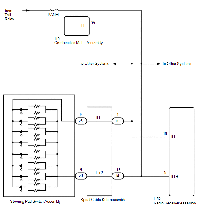
Power is supplied to the radio receiver assembly and steering pad switch assembly when the light control switch is in the tail or head position.
WIRING DIAGRAM
CAUTION / NOTICE / HINT
NOTICE:
The vehicle is equipped with a Supplemental Restraint System (SRS) which includes components such as airbags. Before servicing (including removal or installation of parts), be sure to read the precaution for Supplemental Restraint System.
Click here .gif)
PROCEDURE
| 1. | CHECK METER / GAUGE SYSTEM |
(a) Check if the rheostat function operates normally.
OK:
The rheostat function operates normally.
| NG | .gif) | GO TO METER / GAUGE SYSTEM |
|
.gif)
| 2. | CHECK LIGHTING SYSTEM (INT) |
(a) Check if the instrument panel illumination comes on normally.
OK:
The instrument panel illumination comes on normally.
| NG | | GO TO LIGHTING SYSTEM (INT) |
|
| 3. | CHECK ILLUMINATION |
(a) Check if the illumination for the steering pad switch assembly or radio receiver assembly comes on when the light control switch is turned to the head or tail position.
| Result | Proceed to |
|---|---|
| Illumination for steering pad switch assembly does not come on. | A |
| Illumination for radio receiver assembly does not come on. | B |
| B | | GO TO STEP 7 |
|
| 4. | CHECK HARNESS AND CONNECTOR (ILLUMINATION SIGNAL CIRCUIT) |
| (a) Disconnect the spiral cable sub-assembly connector. |
|
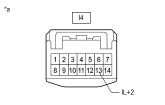
(b) Measure the voltage according to the value(s) in the table below.
Standard Voltage:
| Tester Connection | Switch Condition | Specified Condition |
|---|---|---|
| I4-13 (IL+2) - Body ground | Power switch on (IG) Light control switch in the tail or head position | 11 to 14 V |
| NG | | REPAIR OR REPLACE HARNESS OR CONNECTOR |
|
| 5. | INSPECT STEERING PAD SWITCH ASSEMBLY |
(a) Remove the steering pad switch assembly.
Click here
(b) Inspect the steering pad switch assembly.
Click here
| NG | | REPLACE STEERING PAD SWITCH ASSEMBLY |
|
| 6. | INSPECT SPIRAL CABLE SUB-ASSEMBLY |
(a) Remove the spiral cable sub-assembly.
Click here
(b) Inspect the spiral cable sub-assembly.
Click here
| OK | | REPAIR OR REPLACE HARNESS OR CONNECTOR |
| NG | | REPLACE SPIRAL CABLE SUB-ASSEMBLY |
| 7. | CHECK HARNESS AND CONNECTOR (ILLUMINATION SIGNAL CIRCUIT) |
| (a) Disconnect the radio receiver assembly connector. |
|
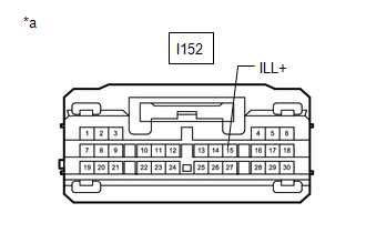
(b) Measure the voltage according to the value(s) in the table below.
Standard Voltage:
| Tester Connection | Switch Condition | Specified Condition |
|---|---|---|
| I152-15 (ILL+) - Body ground | Power switch on (IG) Light control switch in tail or head position | 11 to 14 V |
| NG | | REPAIR OR REPLACE HARNESS OR CONNECTOR |
|
| 8. | CHECK HARNESS AND CONNECTOR (RADIO RECEIVER ASSEMBLY - COMBINATION METER ASSEMBLY) |
(a) Disconnect the I152 radio receiver assembly connector.
(b) Disconnect the I10 combination meter assembly connector.
(c) Measure the resistance according to the value(s) in the table below.
Standard Resistance:
| Tester Connection | Condition | Specified Condition |
|---|---|---|
| I152-16 (ILL-) - I10-39 (ILL-) | Always | Below 1 Ω |
| OK | | PROCEED TO NEXT SUSPECTED AREA SHOWN IN PROBLEM SYMPTOMS TABLE |
| NG | | REPAIR OR REPLACE HARNESS OR CONNECTOR |
READ NEXT:
 Speaker Circuit
DESCRIPTION If there is a short in a speaker circuit, the stereo component amplifier assembly detects it and stops output to the speakers. As a result, sound cannot be heard from the speakers even if
Sound Signal Circuit between Radio Receiver and Stereo Component Amplifier
DESCRIPTION The radio receiver assembly sends a sound signal to the stereo component amplifier assembly via this circuit. The sound signal that is sent is amplified by the stereo component amplifier a
Sound Signal Circuit between Radio Receiver and Stereo Jack Adapter
DESCRIPTION The No. 1 stereo jack adapter assembly sends the sound signal from an external device to the radio receiver assembly via this circuit. The sound signal that has been sent is amplified by t
SEE MORE:
Components
COMPONENTS ILLUSTRATION *1 RAIN SENSOR *2 RAIN SENSOR COVER *3 RAIN SENSOR TAPE - -
Front Lower Suspension Arm
ComponentsCOMPONENTS ILLUSTRATION *1 FRONT LOWER NO. 1 SUSPENSION ARM SUB-ASSEMBLY LH *2 FRONT SUSPENSION CROSSMEMBER SUB-ASSEMBLY N*m (kgf*cm, ft.*lbf): Specified torque * For use with SST RemovalREMOVAL CAUTION / NOTICE / HINT HINT:
Use the same procedure for the RH an
