Lexus NX: Installation
INSTALLATION
PROCEDURE
1. INSPECT COMPRESSOR OIL
| (a) When replacing the compressor assembly with motor with a new one, gradually discharge the inert gas from the service valve, and drain the following amount of oil from the new compressor assembly with motor before installation. Standard: (Oil capacity inside the new compressor assembly with motor: 105 to 135 g (3.7 to 4.8 oz.) - (Remaining oil amount in the removed compressor assembly with motor) = (Oil amount to be removed from the new compressor) NOTICE:
|
|
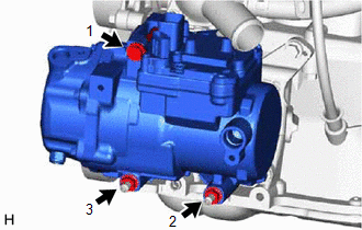
2. INSTALL COMPRESSOR ASSEMBLY WITH MOTOR
(a) Using an E8 "TORX" socket wrench, install the compressor assembly with motor with the 2 stud bolts.
Torque:
9.8 N·m {100 kgf·cm, 87 in·lbf}
| (b) Tighten the bolt and 2 nuts in the order shown in the illustration to install the compressor assembly with motor. Torque: 25 N·m {255 kgf·cm, 18 ft·lbf} |
|
| (c) Connect connector B. |
|
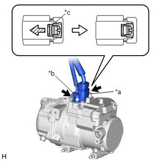
(d) Remove the vinyl tape from connector A.
(e) Connect connector A and slide the green-colored lock as shown in the illustration to lock it securely.
CAUTION:
Make sure to wear insulating gloves.
NOTICE:
Make sure that the connector is connected securely.
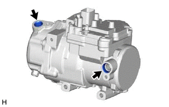
3. CONNECT SUCTION HOSE SUB-ASSEMBLY
(a) Remove the vinyl tape from the suction hose sub-assembly and compressor assembly with motor.
(b) Sufficiently apply compressor oil to a new O-ring and the fitting surface of the suction hose sub-assembly.
Compressor Oil:
ND-OIL 11 or equivalent
(c) Install the O-ring to the suction hose sub-assembly.
NOTICE:
Keep the O-rings and O-ring fitting surfaces free of foreign matter.
(d) Install the suction hose sub-assembly to the compressor assembly with motor with the bolt.
Torque:
9.8 N·m {100 kgf·cm, 87 in·lbf}
4. CONNECT DISCHARGE HOSE SUB-ASSEMBLY
(a) Remove the vinyl tape from the discharge hose sub-assembly and compressor assembly with motor.
(b) Sufficiently apply compressor oil to a new O-ring and the fitting surface of the discharge hose sub-assembly.
Compressor Oil:
ND-OIL 11 or equivalent
(c) Install the O-ring to the discharge hose sub-assembly.
NOTICE:
Keep the O-rings and O-ring fitting surfaces free of foreign matter.
(d) Install the discharge hose sub-assembly to the compressor assembly with motor with the bolt.
Torque:
9.8 N·m {100 kgf·cm, 87 in·lbf}
5. INSTALL REAR ENGINE UNDER COVER LH
Click here .gif)
6. INSTALL REAR ENGINE UNDER COVER RH
Click here
7. INSTALL NO. 1 ENGINE UNDER COVER ASSEMBLY
Click here
8. INSTALL SERVICE PLUG GRIP
Click here
9. INSTALL HYBRID BATTERY SERVICE PLUG COVER
Click here
10. INSTALL BATTERY SERVICE HOLE COVER
Click here
11. CHARGE AIR CONDITIONING SYSTEM WITH REFRIGERANT
Click here
12. WARM UP COMPRESSOR
Click here
13. INSPECT FOR REFRIGERANT LEAK
Click here
READ NEXT:
 Components
COMPONENTS ILLUSTRATION *1 COOLER CONDENSER ASSEMBLY *2 COOLER DRYER *3 DISCHARGE HOSE SUB-ASSEMBLY *4 LIQUID PIPE SUB-ASSEMBLY *5 NO. 1 COOLER CONDENSER CUSHION *6 O-RIN
Removal
REMOVAL PROCEDURE 1. RECOVER REFRIGERANT FROM REFRIGERATION SYSTEM Click here 2. REMOVE RADIATOR ASSEMBLY Click here 3. REMOVE FRONT BUMPER COVER (a) for Sport Package: Click here (b) except Spo
SEE MORE:
Back Door Courtesy Switch Circuit
DESCRIPTION The fold seat control ECU receives the switch operation signal, driving condition signal and back door open/close signal from the back door lock assembly. The fold seat control ECU actives the rear seat according to these signals. WIRING DIAGRAM PROCEDURE 1. CHECK BACK DOOR LOCK A
Oxygen (A/F) Sensor Pumping Current Circuit / Open (for A/F sensor) (Bank 1 Sensor 1) (P2237-P2239,P2252,P2253)
DESCRIPTION Refer to DTC P2195. Click here DTC No. Detection Item DTC Detection Condition Trouble Area MIL Memory P2237 Oxygen (A/F) Sensor Pumping Current Circuit / Open (for A/F sensor) (Bank 1 Sensor 1) An open in the circuit between terminals A1A+ and A1A- of the air fuel
